Bearing producing lathe

A technology of bearing production and lathes, which is applied in the field of bearing production and processing, can solve problems such as jamming, damage of seals, and slowing down of worktable movement speed, so as to achieve the effect of increasing service life and facilitating disassembly and installation

Inactive Publication Date: 2015-09-30
ANHUI QIANSHAN BEARING MFG
View PDF5 Cites 1 Cited by
  • Summary
  • Abstract
  • Description
  • Claims
  • Application Information

AI Technical Summary

Problems solved by technology

[0002] On conventional bearing turning automatic lathes, the connection between the workbench and the hydraulic cylinder is generally a direct connection, that is, the end face of the hydraulic cylinder is directly connected to the end face of the workbench, and the piston rod is directly connected to the base of the workbench, but there are problems with the direct connection. Since the vertical and horizontal lines of the workbench and the hydraulic cylinder cannot be guaranteed to be consistent, using a rigid direct connection will cause the workbench to slow down or even get stuck when it is moving.
The second is that the seals of the hydraulic cylinder will be greatly damaged, causing oil leakage and hydraulic cylinder pressure reduction and other failures.

Method used


Image

  • Bearing producing lathe
  • Bearing producing lathe
  • Bearing producing lathe

Examples


Embodiment Construction

[0013] The following will clearly and completely describe the technical solutions in the embodiments of the present invention with reference to the accompanying drawings in the embodiments of the present invention. Obviously, the described embodiments are only some, not all, embodiments of the present invention. Based on the embodiments of the present invention, all other embodiments obtained by persons of ordinary skill in the art without making creative efforts belong to the protection scope of the present invention.

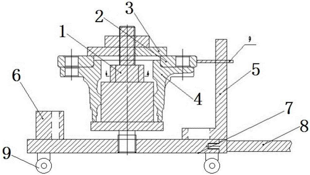
[0014] see Figure 1-4 , in an embodiment of the present invention, a lathe for bearing production includes a guide rail 10, a carriage 1 is movably installed on the guide rail 10, and a workbench 2 is installed on the carriage 1; It is fixedly connected with the hydraulic cylinder 6; one end of the piston rod 4 in the hydraulic cylinder 6 passes through the fixed plate 5 and is connected with one end of the double-ended screw 3, and the other end of the doubl...


PUM


Abstract

A bearing producing lathe comprises a guide rail; a planker is arranged on the guide rail; the guide rail is fixedly connected with a fixing plate; the fixing plate is fixedly connected with a hydraulic cylinder; one end of a piston rod in the hydraulic cylinder is connected with a double-threaded screw after penetrating the fixing plate; the double-threaded screw is connected with the planker and the piston rod; universal wheels are arranged at the bottom of the guide rail; each universal wheel comprises a wheel hull, a bracket, a wheel, a rivet and a lock plate; an insertion hole is formed in the bottom surface of each wheel hull; a slot is formed in each bracket; the bottom end of each rivet extends into the corresponding slot after penetrating the corresponding insertion hole; a friction plate is arranged between the bottom of each slot and the bottom end of the corresponding rivet; a first through hole is formed in the part, in the corresponding slot, of each rivet; a fixing groove and a second through hole are formed in the left side wall and the right side wall of each slot respectively; a groove is formed in the outer side wall of each bracket, and is communicated with the corresponding second through hole; each second through hole is communicated with the corresponding first through hole; each first through hole is communicated with the corresponding fixing groove; the right end of each lock plate is clamped in the corresponding groove; the left end of each lock plate penetrates the corresponding second through hole and the corresponding first through hole sequentially, and is arranged in the corresponding fixing groove.

Description

technical field [0001] The invention relates to the field of bearing production and processing, in particular to a lathe for bearing production. Background technique [0002] On conventional bearing turning automatic lathes, the connection between the workbench and the hydraulic cylinder is generally a direct connection, that is, the end face of the hydraulic cylinder is directly connected to the end face of the workbench, and the piston rod is directly connected to the base of the workbench, but there are problems with the direct connection. Since it is impossible to ensure that the vertical and horizontal lines of the workbench and the hydraulic cylinder are consistent, using a rigid direct connection will cause the workbench to slow down or even get stuck when it is moving. The second is that the seals of the hydraulic cylinder will be greatly damaged, causing oil leakage and hydraulic cylinder pressure reduction and other failures. Contents of the invention [0003] T...

Claims


Application Information

Patent Timeline
Patent Type & Authority Applications(China)
IPC IPC(8): B23B5/00B23Q1/01
CPCB23B5/00B23Q1/017
Inventor 钱宜武钱宜文曹昇胡森王恩德
Owner ANHUI QIANSHAN BEARING MFG
Why Eureka
Try Eureka