Asymmetric backfilling type friction stir spot welding method eliminating holes and annular trenches

A friction stir, asymmetric technology, used in non-electric welding equipment, welding equipment, metal processing equipment, etc., can solve the problems of unable to fill the gap of the stirring sleeve, insufficient plastic metal volume, root holes and surface ring groove defects, etc. Achieve the effect of eliminating holes and surface ring groove defects, compensating for metal volume loss, and eliminating surface ring groove defects

Active Publication Date: 2015-09-30
HARBIN INST OF TECH
View PDF8 Cites 10 Cited by
  • Summary
  • Abstract
  • Description
  • Claims
  • Application Information

AI Technical Summary

Problems solved by technology

[0004] The present invention solves the problem that in the existing symmetrical backfilling friction stir spot welding process, the volume of the remaining plastic metal in the backfilling stage is insufficient to fill

Method used


Image

  • Asymmetric backfilling type friction stir spot welding method eliminating holes and annular trenches
  • Asymmetric backfilling type friction stir spot welding method eliminating holes and annular trenches
  • Asymmetric backfilling type friction stir spot welding method eliminating holes and annular trenches

Examples


specific Embodiment approach 1

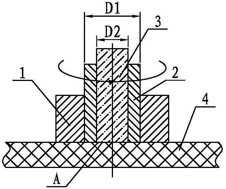
[0020] Specific implementation mode one: combine Figure 1 to Figure 5 Describe this implementation mode, this implementation mode is realized through the following steps:

[0021] Step 1. Set the initial position of the welding tool: put the lower surface of the compression ring 1 in close contact with the upper surface of the plate to be welded 4, and adjust the lower surface of the stirring sleeve 2 and the lower surface of the stirring pin 3 to the compression ring 1. The lower surface is at the same level A, and this level A is set as the zero point of the spot welding process, at the same time, the stirring sleeve 2 and the stirring needle 3 start to rotate; see figure 1 ,

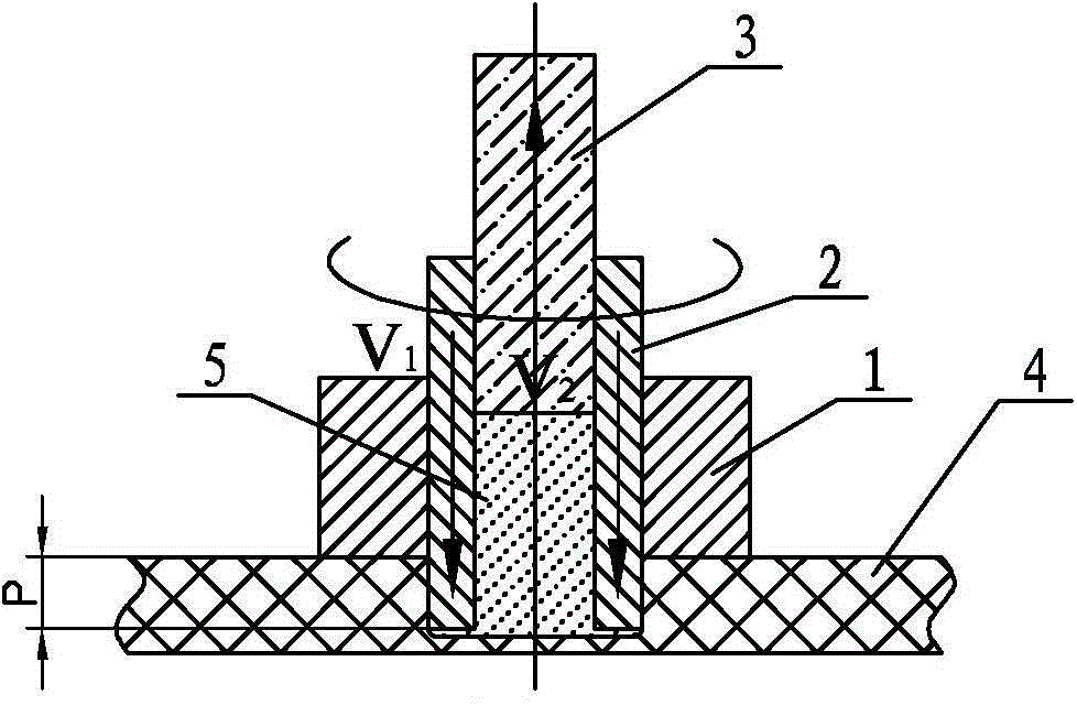
[0022] Step 2. Stirring sleeve 2 pricks down, stirring needle 3 withdraws: Stirring sleeve 2 at speed V 1 Penetrate down into the plate to be welded 4 until it reaches the predetermined penetration depth P, at the same time the stirring needle 3 2 Draw back upwards, so that the volume of the plas...

specific Embodiment approach 2

[0024] Specific implementation mode two: combination figure 2 Describe this embodiment, and this embodiment is the piercing velocity V of stirring sleeve 2 in the step 2 1 0.5mm / s. This lowering speed can make the plastic metal obtain better fluidity. Other components and connections are the same as those in the first embodiment.

specific Embodiment approach 3

[0025] Specific implementation mode three: combination figure 2 Describe this embodiment, and this embodiment is the piercing velocity V of stirring sleeve 2 in the step 2 1 is 1mm / s. This lowering speed can make the plastic metal obtain better fluidity. Other components and connections are the same as those in the first embodiment.


PUM


Abstract

Provided is an asymmetric backfilling type friction stir spot welding method eliminating holes and annular trenches. The method is used for solving the problem that in the process of symmetric backfilling type friction stir spot welding in the prior art, the volume of plastic metal remaining at the backfilling stage is small, a gap generated after back-drawing of a stir sleeve can not be filled, and consequently the defects of root holes or surface annular trenches occur. The method includes the steps that firstly, the initial position of a welding tool is set so that the lower surface of a pressing ring, the lower surface of the stir sleeve and the lower surface of a stir pin can be located in the same horizontal plane as the upper surface of a board to be welded; secondly, dipping of the stir sleeve and back-drawing of the stir pin are performed, and the cavity generated after back-drawing of the stir pin is just filled with plastic metal extruded by the stir sleeve; thirdly, variable-speed backfilling of the plastic metal is performed, and the amount of the plastic metal extruded by the stir pin from the center cavity of the stir sleeve is increased so that the gap generated after back-drawing of the stir sleeve can be better backfilled. Finally, the horizontal position of the lower surface of the stir sleeve and the lower surface of the stir pin is lower than the horizontal position of the upper surface of the board to be welded by a certain distance, so that the metal volume loss is compensated for. The method is used for friction stir spot welding.

Description

technical field [0001] The invention relates to a backfilling friction stir spot welding method, in particular to an asymmetric backfilling friction stir spot welding method for eliminating holes and ring grooves. Background technique [0002] Backfill friction stir spot welding is a new type of solid phase connection technology, which uses split welding tools, including compression rings, stirring sleeves and stirring needles. The spot welding process is divided into two stages: the lowering of the stirring sleeve and the backfilling of the stirring needle: in the lowering stage of the stirring sleeve, the stirring sleeve is inserted into the plate to be welded at a constant speed at a certain speed, and the stirring needle is pulled back at a constant speed at another speed. At this time, the plastic metal stirred by the stirring sleeve enters the cavity of the stirring sleeve left by the withdrawal of the stirring needle; in the backfilling stage of the stirring needle, t...

Claims


Application Information

Patent Timeline
IPC IPC(8): B23K20/12
CPCB23K20/1225
Inventor 赵运强刘会杰杨腾飞胡琰莹刘向前
Owner HARBIN INST OF TECH
Why Eureka
Try Eureka