A large-size bearing dismounting device that helps to improve dismounting efficiency

A high-efficiency, bearing technology, applied in the field of large-size bearing disassembly and assembly devices, can solve the problems of shaft and rolling bearing damage, complex disassembly and assembly tools, and increased production costs, and achieve reliable work, short disassembly and assembly time, and save production costs.

Active Publication Date: 2017-06-30
YUXI DAHONGSHAN MINING
View PDF6 Cites 0 Cited by
  • Summary
  • Abstract
  • Description
  • Claims
  • Application Information

AI Technical Summary

Problems solved by technology

At present, disassembly and assembly tools are generally used to replace rolling bearings and shafts, but the disassembly and assembly tools in the prior art are complicated and have many procedures. It takes 5-6 workers to work continuously for 3 days to complete the disassembly and assembly of a rolling bearing and shaft of a drum, and the disassembly and assembly takes a long time. , the efficiency is low, and the workers are labor-intensive
Moreover, the maintenance is difficult, and the specifications of the tools required for the disassembly and assembly of different types of rollers are different. Multiple sets of tools are required for various types of rollers, which also causes waste in the economy; Causes damage, causing the shaft to be repaired before it can be used, which increases production costs and affects the economic benefits of the enterprise

Method used


Image

  • A large-size bearing dismounting device that helps to improve dismounting efficiency
  • A large-size bearing dismounting device that helps to improve dismounting efficiency
  • A large-size bearing dismounting device that helps to improve dismounting efficiency

Examples


Embodiment Construction

[0019] The present invention will be further described below in conjunction with the accompanying drawings, but the present invention is not limited in any way, and any changes or improvements based on the teaching of the present invention fall within the scope of protection of the present invention.

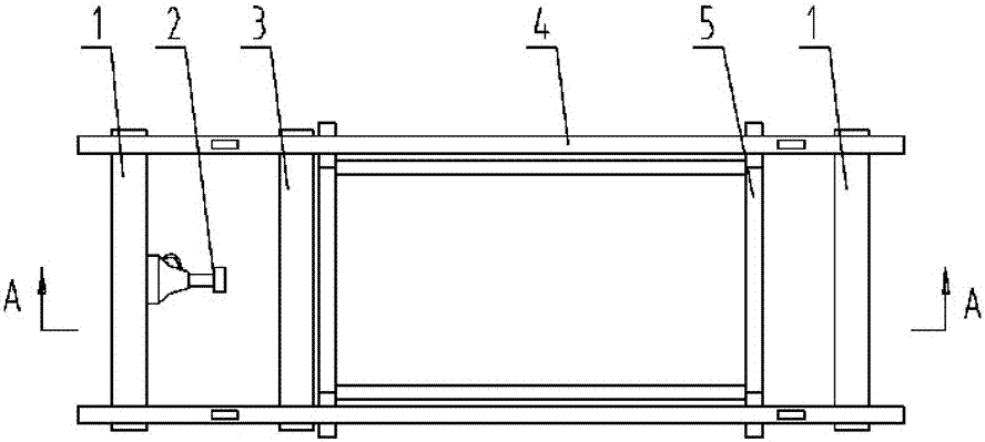
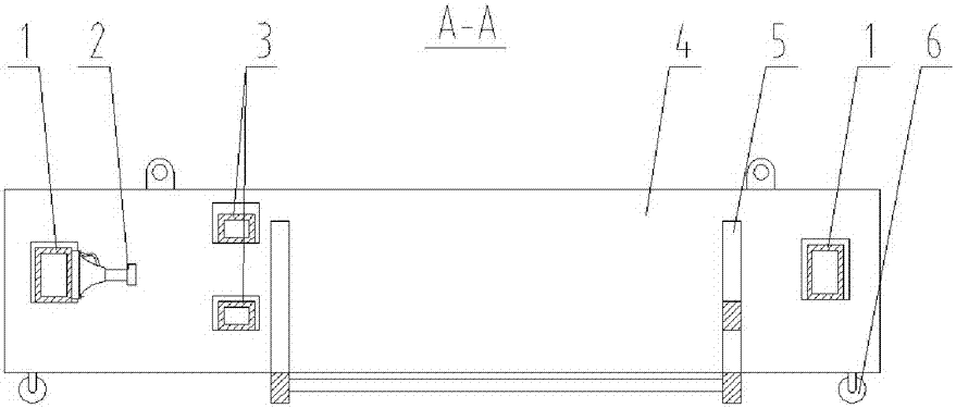
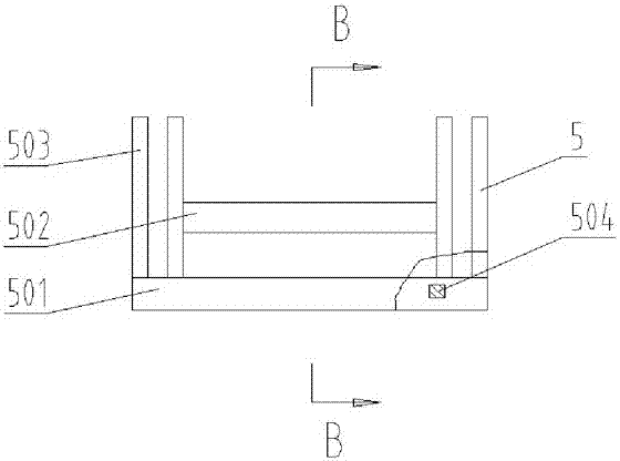
[0020] Such as figure 1 As shown in ~ 8, the present invention comprises a main beam 1, a force applying device 2, an auxiliary beam 3, a vertical plate 4, and a base frame 5, and the two sides of the base frame 5 are respectively provided with a vertical plate 4; Insert into the through groove of the column 503 of the pedestal 5, and they are clearance fit with each other; the two ends of the vertical plate 4 are respectively provided with the main beam 1; A secondary beam 3 is also set between the frames 5; the side of the main beam 1 close to the secondary beam 3 is provided with a force applying device 2, and the bottom of the force applying device 2 is supported and matched...


PUM


Abstract

The invention discloses a large-specification bearing dismounting and mounting device capable of improving the dismounting and mounting efficiency. The large-specification bearing dismounting and mounting device comprises main beams, a force application device, an auxiliary beam, vertical plates and base frames. The vertical plates are arranged on the two sides of the base frames. The vertical plates are inserted into through grooves of vertical columns of the base frames, and the vertical plates are in clearance fit with the through grooves. The main beams are arranged at the two ends of the vertical plates respectively. The auxiliary beam is arranged on the vertical plates and between the main beams and the base frames. The force application device is arranged on the side face, close to the auxiliary beam, of one main beam, wherein the bottom of the force application device and the side face of the main beam are in support fit. The main beams and the auxiliary beam are inserted into rectangular holes of the vertical plates respectively, and the main beams and the auxiliary beam are in clearance fit with the rectangular holes. The structure in which the beams and a hydraulic jack are matched is adopted, bearings are reversely ejected out through thrust of the hydraulic jack, and a shaft is pushed out from the rear end of a roller through the thrust of the hydraulic jack. The large-specification bearing dismounting and mounting device is simple in structure, convenient to use, reliable in work, high in universality and capable of improving the dismounting and mounting efficiency of large-specification bearings conveniently.

Description

technical field [0001] The invention belongs to the technical field of general equipment, and further belongs to the technical field of dismounting devices, and specifically relates to a large-size bearing dismounting device which is simple in structure, convenient to use, reliable in operation, strong in versatility, and helps to improve dismounting efficiency. Background technique [0002] Belt conveyors are widely used in metallurgy, coal, wharf, cement, chemical and other departments because of their advantages such as large conveying capacity, long conveying distance, simple structure, convenient maintenance, low cost and strong versatility. A belt conveyor is a friction driven machine that transports material in a continuous manner. It is mainly composed of frame, conveyor belt, idler roller, transmission roller, tensioning device, transmission device and so on. It can form a material conveying process from the initial feeding point to the final unloading point on a c...

Claims


Application Information

Patent Timeline
Patent Type & Authority Patents(China)
IPC IPC(8): B23P19/027
CPCB23P19/027
Inventor 余正方张坤李雪明王志成徐刚胡远杨国永高伟蔺以伟陈林
Owner YUXI DAHONGSHAN MINING
Why Eureka
Try Eureka