
Automatic control sand blasting machine

A sandblasting machine and sandblasting technology, applied in the field of sandblasting machines, can solve problems such as time-consuming work, inapplicability to products of different specifications, and uncontrollable rotation speed of the turntable, so as to save working time and improve production efficiency

Inactive Publication Date: 2015-09-30
南通华东油压科技有限公司
View PDF5 Cites 9 Cited by
  • Summary
  • Abstract
  • Description
  • Claims
  • Application Information

AI Technical Summary

Problems solved by technology

[0004] Most of the sandblasting machines in the prior art use a large turntable to blast intermittently. However, during the sandblasting process, the rotation speed of the turntable cannot be adjusted, and the spray gun cannot be moved, which makes it unsuitable for products of different specifications.
At present, the dedusting machine used for the existing sandblasting machine adopts a split arrangement and is controlled separately, which increases the cost of manual regulation of the working performance of the sandblasting machine, consumes a lot of working time, and cannot timely monitor the working conditions of each component of the sandblasting machine. make adjustments

Method used


Image

  • Automatic control sand blasting machine
  • Automatic control sand blasting machine

Examples


Embodiment 1

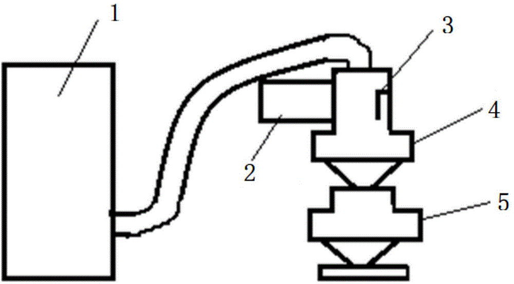
[0024] Such as Figure 1-2 As shown, the present invention provides an automatic control sandblasting machine, comprising a dust collector 1, an electronic control box 2, a sandblasting gun 3, a turntable 4, and an air compressor 5, the turntable 4 is provided with a sealing cover, and the spray The sand gun 3 is arranged in the sealed cover, the dust remover 1 is connected with the sealed cover through a pipeline, the electronic control box 2 is arranged on one side of the sealed cover, and the air compressor 5 is located in the sealed cover. One end of the turntable 4, the sandblasting gun 3 includes a nozzle and a sandblasting pipeline, and the air compressor 5 includes an air intake end and an exhaust end, and the exhaust end is connected with the nozzle through the sandblasting pipeline, The air compressor 5 is used to provide sandblasting power for the sandblasting gun 3 .

[0025] Preferably, a rotating shaft is provided at the center of the turntable 4, the rotating s...

Embodiment 2

[0039] Such as Figure 1-2As shown, the present invention provides an automatic control sandblasting machine, comprising a dust collector 1, an electronic control box 2, a sandblasting gun 3, a turntable 4, and an air compressor 5, the turntable 4 is provided with a sealing cover, and the spray The sand gun 3 is arranged in the sealed cover, the dust remover 1 is connected with the sealed cover through a pipeline, the electronic control box 2 is arranged on one side of the sealed cover, and the air compressor 5 is located in the sealed cover. One end of the turntable 4, the sandblasting gun 3 includes a nozzle and a sandblasting pipeline, and the air compressor 5 includes an air intake end and an exhaust end, and the exhaust end is connected with the nozzle through the sandblasting pipeline, The air compressor 5 is used to provide sandblasting power for the sandblasting gun 3 .

[0040] Preferably, a rotating shaft is provided at the center of the turntable 4, the rotating sh...


PUM


Abstract

The invention provides an automatic control sand blasting machine. The automatic control sand blasting machine comprises a dedusting machine, an electronic control box, a sand blasting gun, a rotary disk and an air compressor, wherein a seal cover is arranged on the rotary disk, the sand blasting gun is arranged in the seal cover, the dedusting machine is connected with the seal cover through a pipeline, the electronic control box is arranged on the one side of the seal cover, the air compressor is located at one end of the rotary disk and comprises an air inlet end and an air outlet end, the air outlet end is connected with a nozzle through a sand blasting pipeline, and the air compressor is used for providing sand blasting power for the sand blasting gun. The electronic control box is internally provided with a controller which can control the dedusting machine to start or to stop, the sand blasting gun to move, the nozzle to start or to stop and rotating speed of the rotary disk and can further control the clearing and exhausting functions of the dedusting machine, and a starting or stopping button is arranged on the electronic control box. All components which are arranged in a separated mode of the sand blasting machine can be controlled by the electronic control box, a large number of time of workers is saved, and the production efficiency of the sand blasting machine is improved.

Description

technical field [0001] The invention relates to the field of sandblasting machines, in particular to an automatic control sandblasting machine. Background technique [0002] The sandblasting machine is a machine that uses compressed air as the power to form a high-speed jet beam to spray the spray material onto the surface of the workpiece to be treated at high speed, so as to change the mechanical properties of the outer surface of the workpiece surface. Due to the impact and cutting effect of the abrasive on the surface of the workpiece, the surface of the workpiece can obtain a certain degree of cleanliness and different roughness, so that the mechanical properties of the surface of the workpiece can be improved, thus improving the fatigue resistance of the workpiece, increasing it and the coating The adhesion between them prolongs the durability of the coating film, and is also beneficial to the leveling and decoration of the coating. It removes impurities, variegated co...

Claims


Application Information

Patent Timeline
IPC IPC(8): B24C3/02B24C5/00B24C9/00
CPCB24C3/02B24C5/00B24C7/0046B24C9/00B24C9/003
Inventor 丁洋丁小虎
Owner 南通华东油压科技有限公司
Features
  • Generate Ideas
  • Intellectual Property
  • Life Sciences
  • Materials
  • Tech Scout
  • Unparalleled Data Quality
  • Higher Quality Content
  • 60% Fewer Hallucinations
Learn More