An injection mold with a combined core-pulling structure of an oil cylinder and slider

A technology of injection mold and core-pulling structure, which is applied in the field of injection molds with a combined core-pulling structure of an oil cylinder and slider, can solve the problems of dispersion of guiding force of inclined guide columns, ineffective movement of sliders, and enlarged mold dimensions. Achieve the effect of increasing mold life, improving overall cost-effectiveness, and reducing overall dimensions

Active Publication Date: 2017-05-31
TAICANG QIUJING PLASTIC MOLD
View PDF4 Cites 0 Cited by
  • Summary
  • Abstract
  • Description
  • Claims
  • Application Information

AI Technical Summary

Problems solved by technology

When the angle between the core-pulling direction of the slider and the vertical direction of the mold opening is greater than or less than 30 degrees, the guiding force of the inclined guide column designed in the mold opening direction will be scattered, and the slider cannot move effectively
If the core pulling of the cylinder is designed in the direction of movement of the slider, the overall size of the mold will become larger, and the tonnage requirements of the mass-produced injection molding machine will increase, resulting in an increase in injection molding costs

Method used


Image

  • An injection mold with a combined core-pulling structure of an oil cylinder and slider
  • An injection mold with a combined core-pulling structure of an oil cylinder and slider

Examples


Embodiment Construction

[0016] In order to make the object, technical solution and advantages of the present invention clearer, the specific implementation manners of the present invention will be described in detail below in conjunction with the accompanying drawings. Examples of these preferred embodiments are illustrated in the accompanying drawings. The embodiments of the invention shown in and described with reference to the drawings are merely exemplary, and the invention is not limited to these embodiments.

[0017] Here, it should also be noted that, in order to avoid obscuring the present invention due to unnecessary details, only the structures and / or processing steps closely related to the solution according to the present invention are shown in the drawings, and the related Other details are not relevant to the invention.

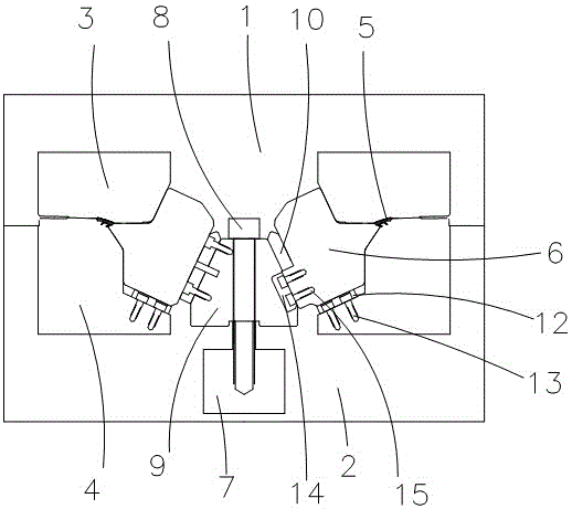
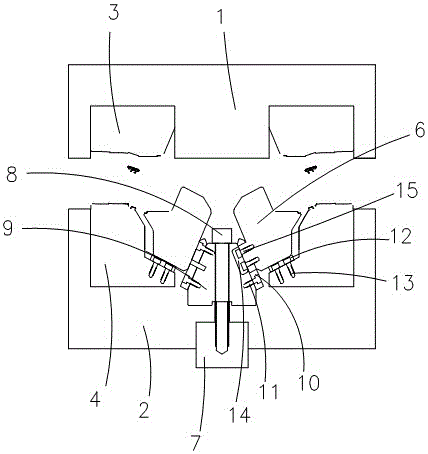
[0018] ginseng figure 1 and figure 2 As shown, an injection mold with an oil cylinder slider combined core-pulling structure includes: a fixed template 1 and a mov...


PUM


Abstract

The invention discloses an injection mold with an oil cylinder slide block combined type core-pulling structure. The injection mold with the oil cylinder slide block combined type core-pulling structure comprises a fixed mold plate and a movable mold plate arranged below the fixed mold plate, wherein a fixed mold core is arranged in the fixed mold plate, a movable mold core is arranged in the movable mold plate, a product cavity and a slide block are arranged between the fixed mold core and the movable mold core, and a core-pulling mechanism is arranged in the movable mold plate. The core-pulling mechanism comprises an oil cylinder, an oil cylinder fixing screw and an oil cylinder stroke guiding block, the oil cylinder is connected with the oil cylinder stroke guiding block through the oil cylinder fixing screw, a first wear-resisting plate is installed on the oil cylinder stroke guiding block, a second wear-resisting plate is installed on the movable mold, a slide block stroke guiding block matched with the first wear-resisting plate is installed on the slide block, therefore, the size of the appearance of the mold is greatly reduced, and the mold space is saved.

Description

technical field [0001] The invention relates to an injection mold, in particular to an injection mold with an oil cylinder slider combined type core-pulling structure. Background technique [0002] Injection mold core pulling is generally realized by slider and inclined top movement. The movement of the slider generally uses the inclined guide post to transmit the guiding force. When the angle between the core-pulling direction of the slider and the vertical direction of mold opening is greater than or less than 30 degrees, the guiding force of the inclined guide column designed in the mold opening direction will be dispersed, and the slider cannot move effectively. If the core-pulling cylinder is designed in the direction of movement of the slider, the overall size of the mold will become larger, and the tonnage requirements of the mass-produced injection molding machine will increase, resulting in an increase in injection molding costs. [0003] Therefore, it is necessar...

Claims


Application Information

Patent Timeline
Patent Type & Authority Patents(China)
IPC IPC(8): B29C45/33B29C45/40
CPCB29C45/332B29C45/40
Inventor 陆瑞卿吴立新
Owner TAICANG QIUJING PLASTIC MOLD
Why Eureka
Try Eureka