Steering device

A technology of steering device and steering shaft, which is applied in the direction of steering mechanism, transmission device, power steering mechanism, etc.

Active Publication Date: 2015-09-30
JTEKT CORP
View PDF6 Cites 7 Cited by
  • Summary
  • Abstract
  • Description
  • Claims
  • Application Information

AI Technical Summary

Problems solved by technology

However, in the case where such a disc spring 142 is used as the elastic member 140, when the bearing 130 moves in the rack shaft axial direction ZA, there is a possibility that the disc spring 142 is deformed to Figure 16B Possibility of clinging states shown

Method used


Image

  • Steering device
  • Steering device
  • Steering device

Examples


Embodiment Construction

[0043] Hereinafter, a first embodiment of the steering apparatus will be described. The steering device of the present embodiment is an electric power steering device in which an assist force is applied to a steering mechanism by a motor.

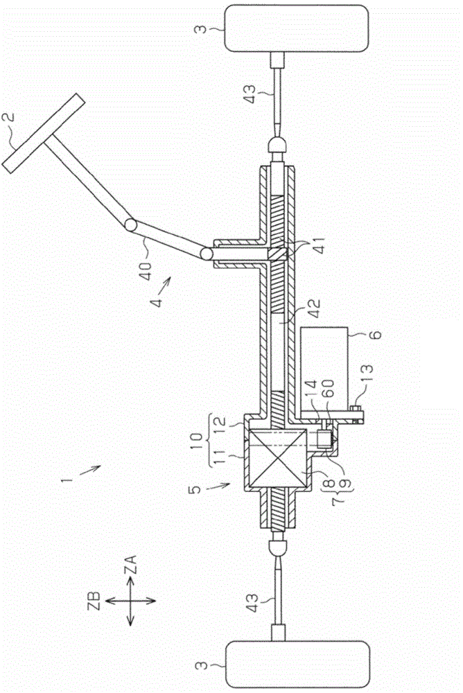
[0044] like figure 1 As shown, the electric power steering device 1 includes a steering mechanism 4 that steers the steered wheels 3 based on the operation of the steering wheel 2 by the driver, and a power assist mechanism 5 that assists the driver's steering operation.

[0045] The steering mechanism 4 includes a steering shaft 40 constituting a rotation shaft of the steering wheel 2 , and a rack shaft 42 connected to a lower end portion of the steering shaft 40 via a rack and pinion mechanism 41 . In the present embodiment, the rack shaft 42 corresponds to a steering shaft. In the steering mechanism 4 , when the steering shaft 40 is rotated according to the operation of the steering wheel 2 by the driver, the rotational motion is conv...


PUM


Abstract

A steering device includes a ball screw mechanism 8 that applies a force in the axial direction to a rack shaft of a vehicle, and a bearing 20 that rotatably supports a nut 80 with respect to a housing 10. The steering device also includes a plate 31 disposed with a gap between the bearing 20 and the plate 31 in a rack shaft axial direction ZA, and a coned disc spring 32 disposed between the bearing 20 and the plate 31. The plate 31 abuts against the housing 10 in the rack shaft axial direction ZA. The coned disc spring 32 elastically supports the nut 80 in the rack shaft axial direction ZA via the bearing 20. One side surface 31c of the plate 31 that faces the coned disc spring 32 is formed in a tapered shape so as to cross a rack shaft radial direction ZB.

Description

[0001] The present application claims priority to Japanese Patent Application No. 2014-064703 filed on March 26, 2014, the entire contents of which include the specification, drawings, and abstract are incorporated herein by reference. technical field [0002] The present invention relates to steering devices. Background technique [0003] As one of the steering devices, there is an electric power steering device including a ball screw mechanism attached to the outer periphery of a rack shaft and a motor coupled to the ball screw mechanism via a reduction mechanism. In this electric power steering apparatus, when the rotation of the output shaft of the motor is transmitted to the ball screw mechanism via the speed reduction mechanism, the ball screw mechanism applies an axial force to the rack shaft. The axial force applied to the rack shaft becomes an assist force, which assists the driver's steering operation. Conventionally, as a support structure of a ball screw mechani...

Claims


Application Information

Patent Timeline
IPC IPC(8): B62D5/04
CPCF16C27/04B62D5/0448F16H25/24F16C19/08F16C2326/24
Inventor 中村隆一山口真司柴田龙司
Owner JTEKT CORP
Why Eureka
Try Eureka