Immersed tube ballast tank and frame thereof

An immersed tube and water tank technology, applied in water conservancy projects, underwater structures, artificial islands, etc., can solve problems such as difficulty in ensuring ballast, inability to ensure the stability of pipe sections and construction safety, and limited water storage.

Inactive Publication Date: 2015-09-30
SHANGHAI TUNNEL ENGINEERING RAILWAY TRANSPORTATION DESIGN INSTITUTE +1
View PDF4 Cites 4 Cited by
  • Summary
  • Abstract
  • Description
  • Claims
  • Application Information

AI Technical Summary

Problems solved by technology

[0007] The present invention aims to solve the problem that the existing immersed tube ballast water tank has limited water storage c

Method used


Image

  • Immersed tube ballast tank and frame thereof
  • Immersed tube ballast tank and frame thereof
  • Immersed tube ballast tank and frame thereof

Examples


Embodiment Construction

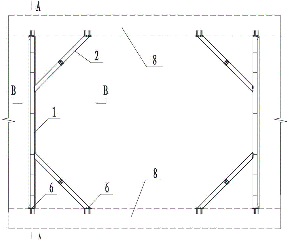
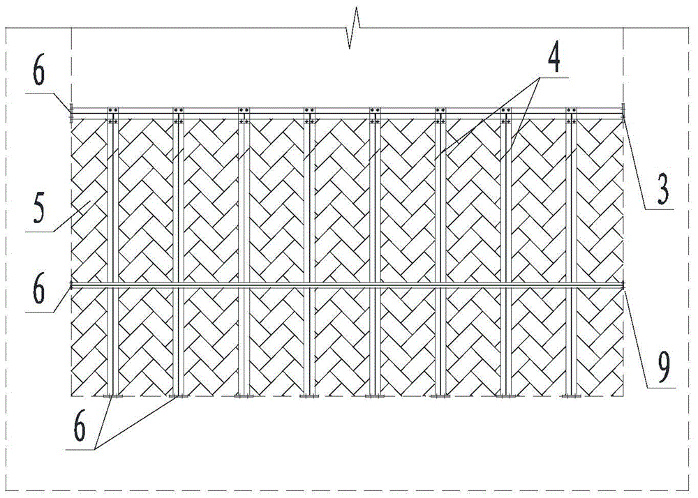
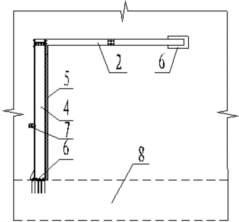
[0029] The specific implementation manners of the present invention will be further described in detail below in conjunction with the accompanying drawings and embodiments. The following examples are used to illustrate the present invention, but are not intended to limit the scope of the present invention.

[0030] In the description of the present invention, unless otherwise specified, the orientation or state relationship indicated by the terms "upper", "lower", "top", "bottom", "longitudinal" etc. is based on the orientation or state relationship shown in the drawings , is only for the convenience of describing the present invention and simplifying the description, but does not indicate or imply that the referred device or element must have a specific orientation, be constructed and operated in a specific orientation, and thus should not be construed as limiting the present invention.

[0031] In the description of the present invention, it should be noted that unless other...


PUM


Abstract

The invention relates to the field of immersed tube tunnels and provides an immersed tube ballast tank and a frame thereof. The immersed tube ballast tank comprises the frame and a waterproof film; the frame comprises two tank-walls arranged at intervals within an immersed tube; the bottoms of the tank-walls are connected with the bottom of the immersed tube; two sides of the tank-walls are connected with two inner walls of the immersed tube, respectively; the waterproof film is paved on the inner sides of the tank-walls and two inner walls of the immersed tube arranged between the tank-walls. The holes of the segment of the immersed tube tunnel are fully distributed in the ballast tank, the existing structure is used to form the two sidewalls of the ballast tank, water storage capacity and ballasting capacity are improved, and the materials for the sidewalls of the tank are saved; the tank is in an assembled structure suitable for reuse, constructability of a scheme is improved, and manufacturing cost is lowered.

Description

technical field [0001] The invention relates to the field of immersed tube tunnels, and in particular provides an immersed tube ballast water tank and its skeleton. Background technique [0002] The ballast water tank is a necessary temporary facility during the installation of each pipe section of the immersed tunnel. The structure of the existing ballast water tank is generally to erect four steel walls on the top surface of the bottom plate of the pipe joint to form a closed body, which is removed after the installation of the pipe joint is completed. The connection between the steel wall and the tunnel floor is usually welded. [0003] Existing ballast tanks mainly have the following disadvantages: [0004] 1. The water storage capacity of the ballast water tank structure is limited, and the ballast provided is small, so it can only be applied to the construction of small-volume pipe-section freshwater environments. When the volume of the pipe joint itself is large, o...

Claims


Application Information

Patent Timeline
IPC IPC(8): E02D29/073
Inventor 陈鸿陈正杰陈华陆明奚程磊季应伟吕勇刚黄清飞
Owner SHANGHAI TUNNEL ENGINEERING RAILWAY TRANSPORTATION DESIGN INSTITUTE
Why Eureka
Try Eureka