Apparatus for connecting deformed bar

A technology for deforming steel bars and connecting devices, which is applied in the construction, building structure, and building material processing, etc., can solve the problems of large operation time, low connection processing cost, and inability to connect, so as to save construction costs, save operation time, The effect of saving time

Inactive Publication Date: 2015-09-30
李宝热
View PDF22 Cites 4 Cited by
  • Summary
  • Abstract
  • Description
  • Claims
  • Application Information

AI Technical Summary

Problems solved by technology

[0006] However, the necessary conditions for the connection of the threaded sleeve to the actual work site, that is, in the surrounding environment of the work site, the deformed steel bar, such as D25*8ra1, weighs about 30-40Kg to be erected vertically, and is lifted about 2m from the ground. And it must be connected on the exact vertical line, but when it is a threaded threaded sleeve, the thread cannot be connected when the thread is not on the exact vertical line. Therefore, the exact vertical connection has the following disadvantages. According to the operator's working attitude or proficiency, it is difficult to connect vertically, and thus prolonging the operation time
[0007] Therefore, when arranging deformed steel bars in joint connection, the connection is the fastest and the connection processing cost is minimized, but the thicker the deformed steel bars, the longer the connection length and the waste of a large amount of material occurs.
In addition, the crimping connection reduces the waste of steel bars and minimizes processing costs or logistics costs, but costs for crimping specialists and crimping engineering are incurred, and a lot of time is required for crimping, and elastic deformation occurs due to heating of steel bars
In addition, the threaded sleeve connection that requires thread processing can minimize the waste of steel bars, but it is not easy to connect when it is not on an accurate horizontal or vertical line, thus requiring a lot of work time, and because before the connection work, it is necessary to Thread processing at the end of the steel bar increases the processing time, cost and logistics costs, and when the thread processing is defective, there is a disadvantage that reprocessing or reordering is required
In addition, the threaded sleeve connection without thread processing can minimize the waste of steel bars and processing costs or logistics costs, but it is difficult for unskilled people to accurately connect the steel bars to the threaded sleeves horizontally or vertically. The working time and the complex structure of the threaded sleeve or the addition of parts make the work cumbersome.

Method used


Image

  • Apparatus for connecting deformed bar
  • Apparatus for connecting deformed bar
  • Apparatus for connecting deformed bar

Examples


no. 1 Embodiment

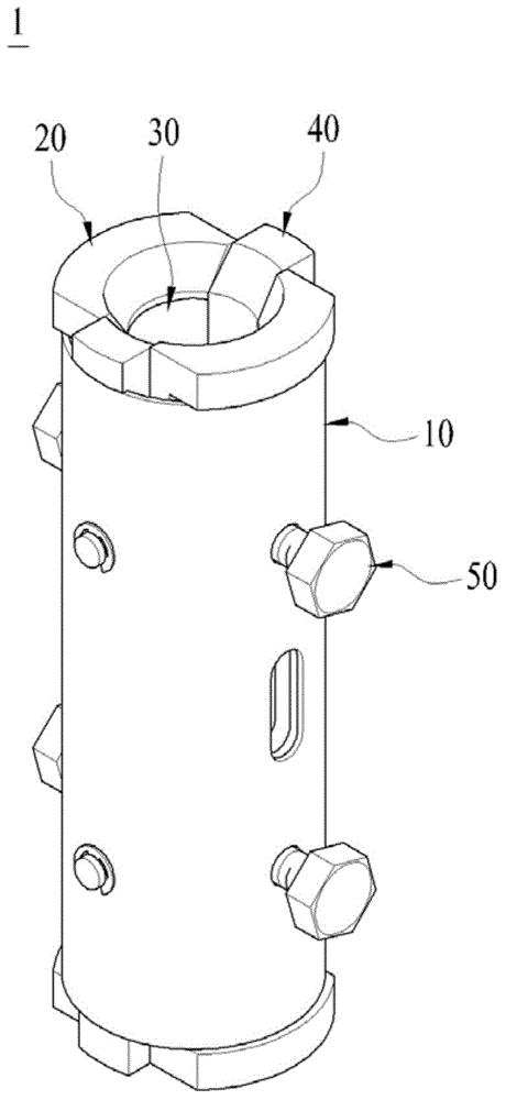
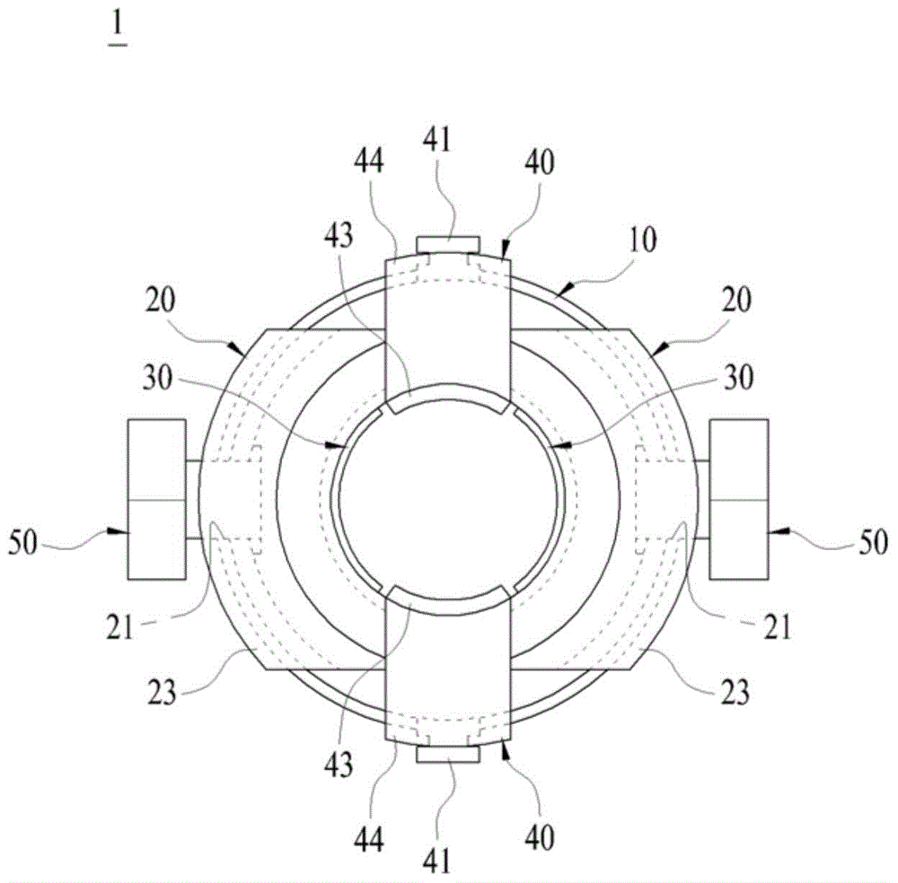
[0060] figure 1 Among them, the connecting device 1 for connecting deformed steel bars has a pair of pressing members 20 and a pair of partition members 40 built in a cylindrical shell 10, the inner surface of the pressing members 20 is joined with a mat 30, and a fixing member 50 is joined. , apply pressure to the pressing parts 20 from the outside, and fix the deformed steel bar between the pressing parts 20 .

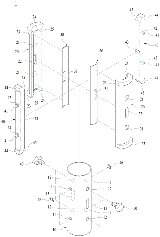
[0061] exist figure 2 , the housing 10 is a cylinder with a predetermined diameter, and a plurality of through holes 11 and fixing holes 12 are formed through the periphery. The through holes 11 are respectively formed in the upper part and the lower part, and are formed through the outer peripheral surface oppositely at an angle of about 180 degrees. The fixing holes 12 are respectively formed in the upper part and the lower part, and formed through the outer peripheral surface oppositely at an angle of about 180 degrees. Therefore, the through hole 11 and the f...

no. 2 Embodiment

[0076]The structural features of the second embodiment include: a cylindrical shell formed with a predetermined diameter, and a plurality of through holes and fixing holes are formed through the periphery, and a plurality of through holes and fixing holes are formed between the through holes and the fixing holes. a through hole; a pair of arc-shaped pressure-applying parts, which are inserted into the housing, with flanges formed on the upper and lower parts, and a plurality of fixing grooves formed on the outer surface; arc-shaped cushions, which are elastic, are joined to the pressure-applying parts The inner surface; a pair of arc-shaped partition parts, inserted between the pair of pressing parts, the upper and lower parts are formed with flanges, and the center of the outer surface protrudes to form a protrusion; the fixing part is screwed through the fixing hole, and the end The part is in contact with the fixing groove; the nut-shaped part has a second through hole insid...


PUM


Abstract

The present invention relates to a coupling device for a deformed bar capable of firmly coupling ends of deformed bars. The coupling device for a deformed bar includes a cylindrical housing having a constant diameter and formed with a plurality of through-holes and fixing holes on the outer circumference thereof; a pair of arc-shaped pressing members inserted into the housing and having flanges at upper and lower portions and a plurality of fixing grooves on the outer surface; an arc-shaped elastic pad coupled to the inner surface of the pressing member; a pair of arc-shaped spacers inserted between the pressing members and having flanges at upper and lower portions and a protrusions protruding from the outer surface; and a fixing member fixed to the fixing hole by a screw, with an end coming into contact with the fixing groove. The deformed bars are inserted and fixed between the pressing members and the spacers from the top and the bottom.

Description

technical field [0001] The present invention relates to a connecting device for deformed bars, and more particularly to a deformed bar connecting device for aligning deformed bars with ends of deformed bars for a stronger joint. Background technique [0002] In general, deformed bars are used in reinforced concrete buildings to form protrusions on the surface of the bar and bond the concrete well. A steel bar with ribs or strips protruding on the surface of deformed steel bars. It is a deformed steel bar that meets the requirements of KSD3504 or a steel bar of the same quality and shape. The bond strength is more than 2 times higher than that of other round steel bars. [0003] Currently, in the process of reinforced concrete construction, in order to connect deformed steel bars of a predetermined length, after the deformed steel bars are stacked, the ends of the deformed steel bars are crimped, that is, welded. The crimp connection method, and the method of connecting defo...

Claims


Application Information

Patent Timeline
Patent Type & Authority Applications(China)
IPC IPC(8): E04G21/12
Inventor 李宝热
Owner 李宝热
Why Eureka
Try Eureka