
Vacuum heat insulation pipe

A technology of vacuum insulation and outer tube, applied in drilling pipe, casing, production fluid, etc., can solve the problems of unfavorable driving of crude oil, reduction of effective latent heat, large loss of dryness, etc., to ensure bottomhole dryness and reduce steam The effect of bypassing flow and reducing hot spot loss

Inactive Publication Date: 2015-09-30
PETROCHINA CO LTD
View PDF6 Cites 2 Cited by
  • Summary
  • Abstract
  • Description
  • Claims
  • Application Information

AI Technical Summary

Problems solved by technology

As a result, the dryness loss of the injected steam in the wellbore is relatively large, and the effective latent heat entering the oil layer is reduced, which is not conducive to the purpose of driving crude oil. At the same time, it is easy to cause damage and deformation of the casing under long-term high temperature and high pressure conditions

Method used


Image

  • Vacuum heat insulation pipe
  • Vacuum heat insulation pipe

Examples


Embodiment Construction

[0014] The following will clearly and completely describe the technical solutions in the embodiments of the present invention with reference to the accompanying drawings in the embodiments of the present invention. Obviously, the described embodiments are only some, not all, embodiments of the present invention. Based on the embodiments of the present invention, all other embodiments obtained by persons of ordinary skill in the art without making creative efforts belong to the protection scope of the present invention.

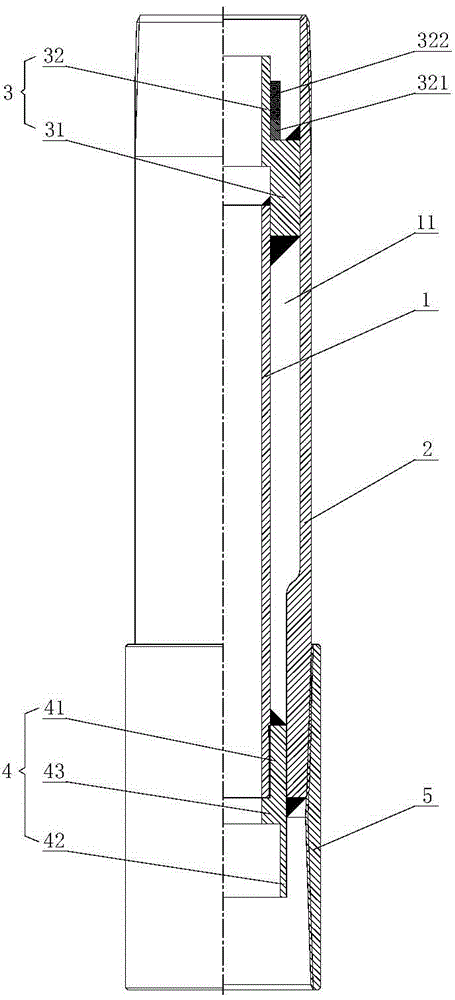
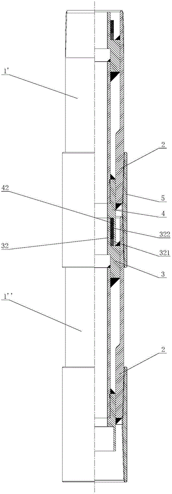
[0015] Such as figure 1 As shown, the present invention provides a vacuum heat insulation pipe, which includes an inner pipe 1 and an outer pipe 2, the inner pipe 1 is penetrated in the outer pipe 2, and one end of the inner pipe 1 is connected to the outer pipe A supporting ring 3 is connected between one end of the inner tube 1, a compression ring 4 is connected between the other end of the inner tube 1 and the other end of the outer tube 2, and a collar is ...


PUM


Abstract

The invention provides a vacuum heat insulation pipe. The vacuum heat insulation pipe comprises an internal pipe and an external pipe, wherein the internal pipe is arranged in the external pipe in a penetrating mode, a supporting ring is connected between one end of the internal pipe and one end of the external pipe, a compression ring is connected between the other end of the internal pipe and the other end of the external pipe, and the outer side of the other end of the external pipe is connected with a coupling. In the process of continuously injecting steam for a long term, by means of the vacuum heat insulation pipe, the heat loss at the coupling position of the vacuum heat insulation pipe can be effectively reduced, and the goal of improving the heavy oil reservoir employing degree is achieved.

Description

technical field [0001] The invention relates to a heat insulation pipe, in particular to a vacuum heat insulation pipe used in the technical field of heavy oil thermal recovery. Background technique [0002] Heavy oil reservoirs in Liaohe Oilfield are generally buried deep. For medium-deep heavy oil reservoirs, the heat insulation effect of steam injection pipe strings has not been ideal. There are problems such as bypass flow, leakage and decompression when steam passes through heat-insulated pipe couplings. The heat insulation pipe coupling still becomes one of the main heat dissipation points of the steam drive pipe string. As a result, the dryness loss of the injected steam in the wellbore is relatively large, and the effective latent heat entering the oil layer is reduced, which is not conducive to the purpose of driving crude oil. At the same time, it is easy to cause damage and deformation of the casing under long-term high temperature and high pressure conditions. ...

Claims


Application Information

Patent Timeline
Patent Type & Authority Applications(China)
IPC IPC(8): E21B17/00E21B17/02E21B43/24
Inventor 陈鹏赵旭亮田野范嘉瑞张涵淇施玉张建高春阳陈辽望黄小钊孔凡楠徐晶董亮
Owner PETROCHINA CO LTD
Learn More