Check patentability & draft patents in minutes with Patsnap Eureka AI!

System and method for improving the response time of an engine using model predictive control

A model predictive control, engine technology, applied in general control systems, control/regulation systems, combustion engines, etc., can solve problems such as accurately controlling engine output torque

Active Publication Date: 2015-09-30
GM GLOBAL TECH OPERATIONS LLC
View PDF19 Cites 12 Cited by
  • Summary
  • Abstract
  • Description
  • Claims
  • Application Information

AI Technical Summary

Problems solved by technology

However, conventional engine control systems do not control engine output torque as precisely as needed
Additionally, conventional engine control systems do not provide quick response to control signals or coordinate engine torque control among various devices that affect engine output torque

Method used


Image

  • System and method for improving the response time of an engine using model predictive control
  • System and method for improving the response time of an engine using model predictive control
  • System and method for improving the response time of an engine using model predictive control

Examples


Embodiment Construction

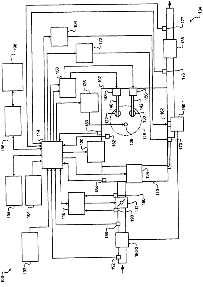
[0065] The engine control module (ECM) controls the torque output of the engine. More specifically, the ECM determines a target value based on the requested amount of torque and controls the engine's actuators based on the target value. For example, the ECM controls intake and exhaust camshaft phasers based on target phaser angles, throttle valve based on target throttle opening area, exhaust gas recirculation (EGR) valve based on target EGR opening, and based on target wastegate The duty cycle controls the wastegate of the turbocharger. The ECM also controls spark timing based on the target spark timing and controls fueling based on the target fueling parameters.

[0066] The ECM may individually use multiple single-input single-output (SISO) controllers, such as proportional-integral-derivative (PID) controllers, to determine the target value. However, when using multiple SISO controllers, target values ​​can be set to maintain system stability at the expense of possible f...


PUM


Abstract

A system according to the principles of the present disclosure includes a model predictive control (MPC) module and an actuator module. The MPC module generates predicted parameters based on a model of a subsystem and a set of possible target values. The MPC module generates a cost for the set of possible target values based on the predicted parameters and at least one of weighting values and references values. The MPC module adjusts the at least one of the weighting values and the reference values based on a desired rate of change in an operating condition of the subsystem. The MPC module selects the set of possible target values from multiple sets of possible target values based on the cost. The actuator module adjusts an actuator of the subsystem based on at least one of the target values.

Description

[0001] Cross References to Related Applications [0002] This application is related to U.S. Patent Application No. 14 / 225,502, filed March 26, 2014, U.S. Patent Application No. 14 / 225,516, filed March 26, 2014, U.S. Patent Application No. 14 / 225,569, filed March 26, 2014 , U.S. Patent Application No. 14 / 225,626, filed March 26, 2014, U.S. Patent Application No. 14 / 225,817, filed March 26, 2014, U.S. Patent Application No. 14 / 225,896, filed March 26, 2014, 2014 U.S. Patent Application No. 14 / 225,531 filed March 26, 2014, U.S. Patent Application No. 14 / 225,507, filed March 26, 2014, U.S. Patent Application No. 14 / 225,808, filed March 26, 2014, March 2014 U.S. Patent Application No. 14 / 225,492, filed March 26, 2014, U.S. Patent Application No. 14 / 226,006, filed March 26, 2014, U.S. Patent Application No. 14 / 226,121, filed March 26, 2014, March 26, 2014 U.S. Patent Application No. 14 / 225,496 filed on March 26, 2014 and U.S. Patent Application No. 14 / 225,891 filed on March 26, 2014...

Claims


Application Information

Patent Timeline
IPC IPC(8): F02D13/00F02D9/00F02D17/02F02D41/00F02D41/30F02D23/00F02B37/18F02P5/04F02D43/00
CPCF02D28/00F02D13/0238F02D11/105F02D41/0002F02D41/005G05B13/048F02D2041/001F02D2041/0017F02D2041/1412F02D2041/1433Y02T10/12Y02T10/40
Inventor G·R·小齐甘J·R·贝尔德霍N·金A·本波拉D·伯纳迪尼
Owner GM GLOBAL TECH OPERATIONS LLC
Features
  • R&D
  • Intellectual Property
  • Life Sciences
  • Materials
  • Tech Scout
  • Unparalleled Data Quality
  • Higher Quality Content
  • 60% Fewer Hallucinations
Learn More