Testing device and method for bond stress between steel strand and concrete in pre-tensioning-method member

A bonding stress and testing device technology, applied in the direction of measuring devices, mechanical devices, instruments, etc., can solve the problem that it is difficult to accurately control the moment when the bond between the steel strand and the concrete fails, and it is difficult to measure the bond between the steel strand and the concrete Stress prestress and other problems, to achieve the effect of accurate and reliable test data, convenient measurement and simple structure

Active Publication Date: 2015-09-30
CHANGAN UNIV
View PDF3 Cites 4 Cited by
  • Summary
  • Abstract
  • Description
  • Claims
  • Application Information

AI Technical Summary

Problems solved by technology

The pull-out mechanism of the two is slightly different, but the application of the direct pull-out test for analysis is simple and accurate enough
[0004] At present, there are few test devices for the bond stress between steel strand and concrete in pre-tensioned members, and for pre-tensioned concrete members, it relies on the bond between steel strand and concrete to apply precompressive stress to concrete, but in In engineering, it is difficult to measure the bond stress between the steel strand and concrete to control the size of the prestress, so that it is difficult to accurately control the moment when the bond between the steel strand and concrete fails. Apparatus for Bonding Stress Between Steel Strand and Concrete in French Components

Method used


Image

  • Testing device and method for bond stress between steel strand and concrete in pre-tensioning-method member
  • Testing device and method for bond stress between steel strand and concrete in pre-tensioning-method member
  • Testing device and method for bond stress between steel strand and concrete in pre-tensioning-method member

Examples


Embodiment 1

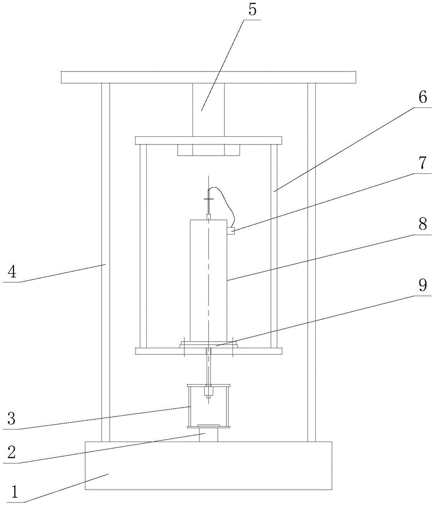
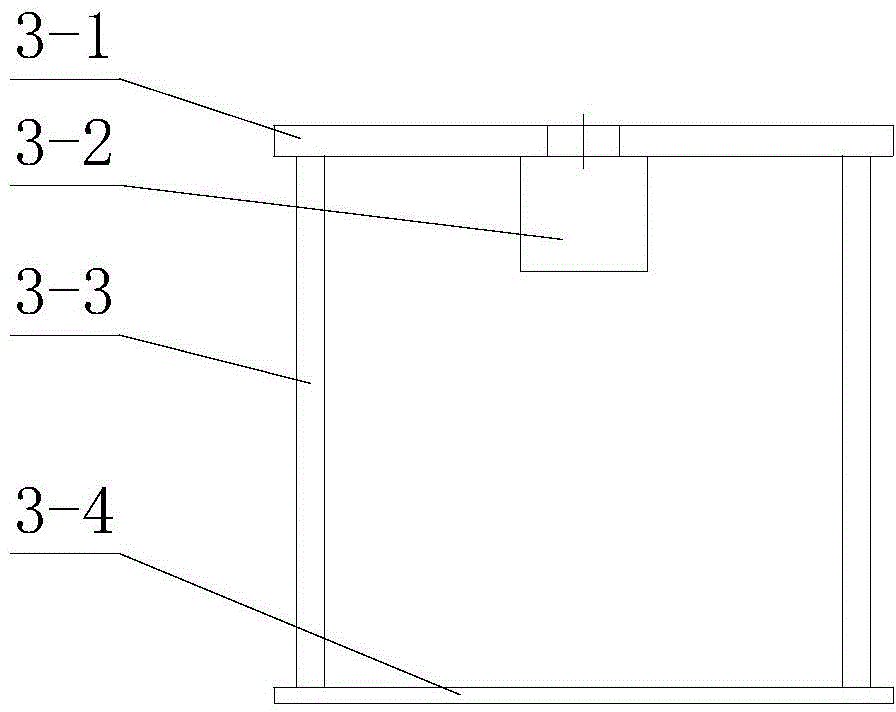
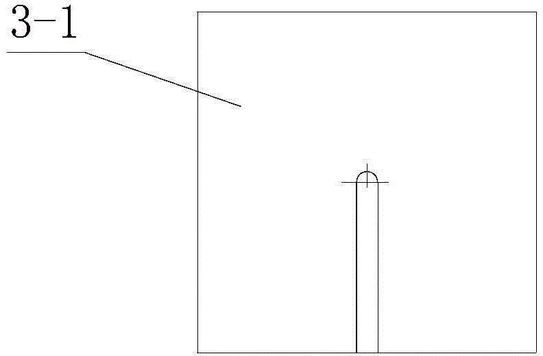
[0021] Depend on figure 1 It can be seen that the bond stress test device between the steel strand and the concrete in the pretensioned member of the present embodiment is composed of a base 1, a hydraulic cylinder 2, a force transmission assembly 3, a support frame 4, a load cell 5, and a sleeve placement frame 6 , sleeve 7, displacement sensor 8 and backing plate 9 are connected to form.

[0022] The base 1 of this embodiment is a cuboid structure, which is used to fix an installation platform of the overall device. A steel strand tensioning mechanism is installed on the base 1. The steel strand tensioning mechanism is mainly capable of placing the pretensioned member to be tested The test platform for fixing the concrete and applying load to the steel strand mainly includes a hydraulic cylinder 2 that can provide the driving force of the load and a support frame 4 that can provide an installation environment for the device that fixes the concrete part of the pretensioned me...

Embodiment 2

[0028] In the test device of the present embodiment, the thickness of the backing plate 9 is 1cm, and the side length is 120mm. There is a steel sleeve 7, the bottom of the sleeve 7 is a square steel plate as large as the backing plate 9, and its four corners pass through the backing plate 9 and the bottom of the sleeve placement frame 6 with threaded fasteners to fasten on the sleeve. On the frame 6, the height h of the sleeve 7 and its diameter d meet: h / d=3 and the diameter d of the sleeve 7 and the maximum particle size d′ of the concrete aggregate in the pretensioned member to be tested The ratio satisfies: d / d′=2.5, that is, the diameter d of the sleeve 7 used in this embodiment is 10 cm, and the height h is 30 cm.

[0029] Other components and their connections are the same as those in Embodiment 1.

[0030] In the method for testing the bonding stress between the steel strand and concrete in the pretensioned member with the test device, step (1) is to fix the steel stra...

Embodiment 3

[0034] In the test device of the present embodiment, the thickness of the backing plate 9 is 2cm, and the side length is 20cm. There is a steel sleeve 7, the bottom of the sleeve 7 is a square steel plate as large as the backing plate 9, and its four corners pass through the backing plate 9 and the bottom of the sleeve placement frame 6 with threaded fasteners to fasten on the sleeve. On the frame 6, the height h of the sleeve 7 and its diameter d meet: h / d=5 and the diameter d of the sleeve 7 and the maximum particle size d′ of the concrete aggregate in the pretensioned member to be tested The ratio satisfies: d / d = 4.5, that is, the diameter d of the sleeve 7 used in this embodiment is 18 cm, and the height h is 90 cm.

[0035] Other components and their connections are the same as those in Embodiment 1.

[0036] The method for testing the bonding stress between the steel strands of the pretensioned member and the concrete using the testing device is also the same as in Exa...


PUM

PropertyMeasurementUnit
Thicknessaaaaaaaaaa
Thicknessaaaaaaaaaa
Side lengthaaaaaaaaaa

Abstract

The invention relates to a testing device and method for bond stress between a steel strand and concrete in a pre-tensioning-method member. According to the device, a force measuring sensor for detecting the bond stress between the steel strand and the concrete in the pre-tensioning-method member is arranged on the top of a supporting frame; a sleeve placing frame is arranged at the bottom of the force measuring sensor; a sleeve for fixing the pre-tensioning-method member is arranged at the center of the bottom of the sleeve placing frame; the sleeve is fixed by the sleeve placing frame; a downward pull force load is applied to the steel strand in the pre-tensioning-method member by using a force transferring assembly, the load and the displacement of the steel strand are recorded in real time by the force measuring sensor and a displacement sensor, so as to determine the load corresponding to the moment of bonding failure between the steel strand and the concrete, test data are relatively accurate and reliable, the measuring error is greatly reduced, and a reliable evidence for the application and the design of the pre-tensioning-method member is provided.

Description

technical field [0001] The invention belongs to stress test equipment, in particular to a device and method for testing bond stress between steel strands and concrete in pretensioned components. Background technique [0002] For pretensioned members, prestressing is applied to the concrete by means of the bonding of concrete and steel strands. By measuring the bonding stress is the basic premise of controlling the pre-compressive stress, it is of great significance to study the tension control stress of pre-tensioned members. [0003] Since bonding is a very complex interaction, it is difficult to achieve better results from the perspective of mechanism, so the position of bonding test research is irreplaceable. There are two main types of test methods commonly used at present: direct pull-out test and bending pull-out test. The pull-out mechanism of the two is slightly different, but the application of the direct pull-out test for analysis is simple and accurate enough. ...

Claims


Application Information

Patent Timeline
IPC IPC(8): G01N19/04
Inventor 任更锋王春生邹存俊徐岳王建华马先坤张锦凯高鹏飞常仕东陈浩
Owner CHANGAN UNIV
Why Eureka
Try Eureka