Aerial environment monitoring terminal and environmental emergency monitoring and deploying system

An environmental monitoring and deployment system technology, applied in the field of aerial environmental monitoring terminals and environmental emergency monitoring and deployment systems, can solve problems such as the inability to guarantee safety, the inability to clarify the source and diffusion of gaseous pollutants, and the inability to carry out effective monitoring. The effect of moderate weight, safety of personnel and good portability

Inactive Publication Date: 2015-09-30
大连市环境监测中心
View PDF7 Cites 17 Cited by
  • Summary
  • Abstract
  • Description
  • Claims
  • Application Information

AI Technical Summary

Problems solved by technology

At present, the existing environmental monitoring instruments have the following problems: there is a lack of corresponding monitoring methods for high-altitude air pollutants, and the source and diffusion of gaseous pollutants cannot be clearly explained in many cases; for environmental events such as explosions and fires or the presence of toxic and harmful gases, monitoring personnel are needed Carrying instruments and equipment close to dangerous areas, safety cannot be guaranteed; for environmental events that require long-term continuous monitoring, relying on monitoring personnel to take turns on duty, the continuity and objectivity of monitoring cannot be guaranteed; for high-altitude emissions of gaseous pollutants and areas that are difficult for personnel to reach , it is basically impossible to carry out effective monitoring

Method used


Image

  • Aerial environment monitoring terminal and environmental emergency monitoring and deploying system
  • Aerial environment monitoring terminal and environmental emergency monitoring and deploying system
  • Aerial environment monitoring terminal and environmental emergency monitoring and deploying system

Examples


Embodiment Construction

[0029] In order to make the purpose, technical solutions and advantages of the embodiments of the present invention clearer, the technical solutions in the embodiments of the present invention will be clearly and completely described below in conjunction with the drawings in the embodiments of the present invention. Obviously, the described embodiments It is a part of embodiments of the present invention, but not all embodiments. Based on the embodiments of the present invention, all other embodiments obtained by persons of ordinary skill in the art without creative efforts fall within the protection scope of the present invention.

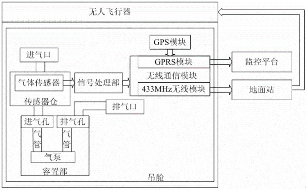
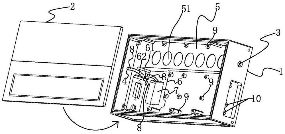
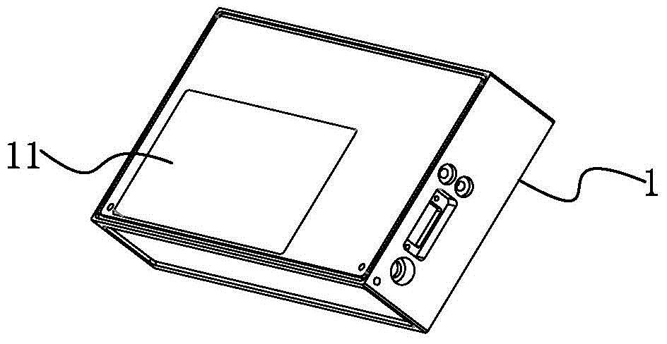
[0030] Such as figure 1 , figure 2 and image 3 A kind of air environment monitoring terminal shown, comprises: unmanned aerial vehicle; The pod installed on the unmanned aerial vehicle; The pod includes a cabin body 1 and a cover plate 2 covered on the cabin body 1; The air inlet 3 and the exhaust port 4 on the cabin body 1; the sensor wareho...


PUM


Abstract

The invention discloses an aerial environment monitoring terminal and an environmental emergency monitoring and deploying system. The aerial environment monitoring terminal comprises an unmanned aerial vehicle, a pod, an air inlet, an air outlet, a sensor cabin, a holding portion, a signal processing portion, a GPS (global positioning system) module and a wireless communication module, wherein the pod is mounted on the unmanned aerial vehicle and comprises a pod body and a cover plate covering the pod body, the air inlet and the air outlet are formed in the pod body, the sensor cabin is arranged in the pod body and communicated with the air inlet, the holding portion is arranged in the pod body and used for holding an air pump, and the signal processing portion is arranged in the pod body. The aerial environment monitoring terminal and the environmental emergency monitoring and deploying system have the advantages that a monitoring means aiming at upper atmosphere pollutants is provided, and upper-air gaseous pollutant emission areas that personnel cannot reach can be monitored effectively.

Description

technical field [0001] The invention relates to the technical field of environmental monitoring, in particular to an aerial environmental monitoring terminal and an environmental emergency monitoring deployment system. Background technique [0002] Environmental emergency monitoring is an important basis and scientific basis for the response and disposal of environmental incidents. It is very important to respond to environmental incidents in a timely and scientific manner by rushing to the scene, conducting monitoring and reporting information as soon as possible. At present, the existing environmental monitoring instruments have the following problems: there is a lack of corresponding monitoring methods for high-altitude air pollutants, and the source and diffusion of gaseous pollutants cannot be clearly explained in many cases; for environmental events such as explosions and fires or the presence of toxic and harmful gases, monitoring personnel are needed Carrying instrum...

Claims


Application Information

Patent Timeline
IPC IPC(8): G05B19/04G01N33/00G01S19/42
CPCG01N33/0004G01S19/42G05B19/04
Inventor 李强丁超王日东徐辉宋维民
Owner 大连市环境监测中心
Why Eureka
Try Eureka