
Lathe top rotation real-time monitoring device

A real-time monitoring and cutting-edge technology, applied in the field of lathe monitoring system, can solve problems such as out-of-sync, unmonitored and protected, consequences or processing quality problems of top workpieces, and achieve the effect of adding alarm function and avoiding major accidents

Active Publication Date: 2018-03-23
SINOSTEEL XINGTAI MACHINERY & MILL ROLL
View PDF6 Cites 0 Cited by
  • Summary
  • Abstract
  • Description
  • Claims
  • Application Information

AI Technical Summary

Problems solved by technology

[0002] In the process of lathe processing, after the top of the tailstock part of the lathe is pressed against the workpiece, its rotation state has been manually observed, or the abnormality can only be found after quality problems occur during the processing. If the spindle of the tailstock sleeve is stuck and the top is not Rotation or asynchronous phenomenon with the workpiece, especially after the tip is hot-melted, it will have very serious consequences or processing quality problems
In the current lathe manufacturing industry, this part is not monitored and protected

Method used


Image

  • Lathe top rotation real-time monitoring device

Examples


Embodiment Construction

[0015] The preferred embodiments of the present invention will be described in detail below with reference to the accompanying drawings.

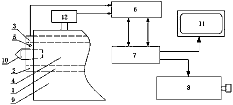
[0016] figure 1 It is a structural schematic diagram of the real-time monitoring device for the top rotation of the lathe of the present invention. As shown in the figure, a real-time monitoring device for the top rotation of the lathe includes a rotation monitoring switch 3 installed on the end cover 2 of the tailstock sleeve 1 and a rotation monitoring switch 3 set on the tailstock sleeve 1. The detection hole 5 on the main shaft 4, the detection hole 5 is facing the rotation monitoring switch 3, and the rotation monitoring switch 3 sends the main shaft rotation signal to the PLC module 6, and the PLC module 6 controls the rotation of the main shaft motor 8 through the numerical control system 7 ( Among the figure, 9 is the tailstock body, and 10 is the top). During equipment processing, after the PLC module 6 detects that the spindle ro...


PUM


Abstract

The invention discloses a real-time monitoring device for the rotation of a lathe centre. The real-time monitoring device comprises a rotary monitoring switch and a detection hole, wherein the rotary monitoring switch is arranged on an end cover of a tailstock sleeve; the detection hole is formed in a tailstock spindle and is right opposite to the rotary monitoring switch; a spindle rotating signal is transmitted to a PLC (Programmable Logic Controller) module by the rotary monitoring switch; the PLC module controls a spindle motor to rotate through a numerical control system. According to the real-time monitoring device disclosed by the invention, the rotation of the spindle can be detected, the spindle rotating signal is transmitted to the PLC module, and the PLC module is enabled to control the spindle motor to rotate through the numerical control system; automatic stopping can be realized when the abnormality occurs, so that major accidents are avoided; meanwhile, after the spindle rotating signal is transmitted to the PLC module, a PLC program can be written, so that the PLC module can control a display screen through the numerical control system to display alarm information.

Description

technical field [0001] The invention relates to a lathe monitoring system, in particular to a real-time monitoring device for the top rotation of a lathe. Background technique [0002] In the process of lathe processing, after the top of the tailstock part of the lathe is pressed against the workpiece, its rotation state has been manually observed, or the abnormality can only be found after quality problems occur during the processing. If the spindle of the tailstock sleeve is stuck and the top is not Rotation or asynchronous phenomenon with the workpiece, especially after the tip is hot-melted, it will have very serious consequences or processing quality problems. In the current lathe manufacturing industry, this part is not monitored and protected. Contents of the invention [0003] In view of this, the purpose of the present invention is to provide a real-time monitoring device for the rotation of the top of the lathe, which can monitor the movement of the top of the l...

Claims


Application Information

Patent Timeline
Patent Type & Authority Patents(China)
IPC IPC(8): G05B19/406
CPCG05B19/406
Inventor 王鸿明邓震文岳文刚岳学锋赵晓光司聚朝张永生
Owner SINOSTEEL XINGTAI MACHINERY & MILL ROLL
Learn More