
Dynamic modeling method of multi-transmission rotor hub structure

A dynamic modeling, rotor hub technology, applied in special data processing applications, instruments, electrical digital data processing, etc., can solve the problem of not carrying out multi-channel force transmission rotor hub configuration design research and other issues

Active Publication Date: 2015-09-30
CHINA HELICOPTER RES & DEV INST
View PDF2 Cites 2 Cited by
  • Summary
  • Abstract
  • Description
  • Claims
  • Application Information

AI Technical Summary

Problems solved by technology

[0004] At present, the configuration design of the domestic helicopter rotor hub is mainly aimed at the articulated type, the most typical is the spherical flexible hub configuration, and no research has been carried out on the configuration design of the multi-way force transmission rotor hub.

Method used


Image

  • Dynamic modeling method of multi-transmission rotor hub structure
  • Dynamic modeling method of multi-transmission rotor hub structure
  • Dynamic modeling method of multi-transmission rotor hub structure

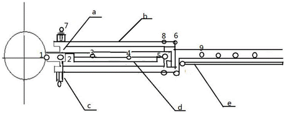
Examples


Embodiment Construction

[0023] The method for dynamic modeling of the multi-way power transmission rotor hub structure involved in the present invention will be further described in detail below in conjunction with the accompanying drawings.

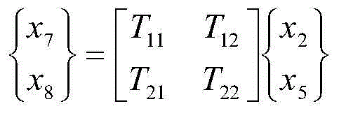
[0024] In the multi-path force transmission rotor hub structural dynamics modeling method of the present invention, the multi-channel force transmission rotor hub structural dynamics finite element modeling is performed first. According to the force transmission, movement and deformation conditions of the components of the propeller hub structure (flexible beam, sleeve, damper and pitch control system), the components are simulated by beam elements, rod elements and elastic damping elements. According to the flexible beam The characteristics of the main force transmission route of the hub with the outer end of the sleeve, the auxiliary force transmission route of the damper and the pitch control system, and the displacement of the connection points between the f...


PUM


Abstract

The invention belongs to a dynamic design technique of helicopters, relates to a dynamic modeling method of a multi-transmission rotor hub structure and aims to prevent ground resonance of a bearingless rotor and expand the air resonance boundary. The accurate modeling analysis and design means is provided in terms of rigidity configuration, displacement coordination for a flexible beam, a control lever, a damper and a sleeve; dynamic finite element modeling of a multi-transmission rotor hub structure is performed first, and degrees of freedom of non-dependent joints of component parts of the structure are expressed in joint degree-of-freedom linearity; according to the dependency and relativeness of the joint degrees of freedom of the component parts of the structure, the independent joints, the relative joints and the displacement coordination relation between the component parts of the structure and the connective joints are determined so as to establish a dynamic rigidity matrix of the structure. By the use of the dynamic modeling method, the key difficulties in the design and analysis of the complex multi-transmission rotor hub structure are broken through.

Description

technical field [0001] The invention belongs to the design technology of helicopter dynamics, and relates to a dynamic modeling method of multi-way force transmission rotor hub structure. Background technique [0002] Bearingless rotor is currently the most advanced structure type of helicopter rotor, which uses composite material flexible beam to replace the horizontal hinge, vertical hinge and axial hinge of traditional articulated rotor hub. On the one hand, when the flexible beam bears the centrifugal load of the blade, it can use the deformation of the degrees of freedom of flapping, shimmy, and torsion to realize the flapping, shimmy, and pitch-changing motion required by the blade, and the deformation is complex; at the same time, because the flexible beam Provides greater flapping and shimmy stiffness for high handling efficiency and shimmy frequency. In order to provide sufficient damping to eliminate ground resonance and air resonance instability, artificial dampe...

Claims


Application Information

Patent Timeline
Patent Type & Authority Applications(China)
IPC IPC(8): G06F17/50
Inventor 凌爱民朱艳钱峰
Owner CHINA HELICOPTER RES & DEV INST
Learn More