Rotary socket

A socket and rotating sleeve technology, applied in flexible/rotatable wire connectors, electrical components, circuits, etc., can solve the problems of complex assembly process, poor strength, and many structural parts, and achieve simple assembly process and high assembly efficiency. , the effect of less structural parts

Inactive Publication Date: 2015-09-30
宁波市镇海乌托邦工业设计有限公司
View PDF10 Cites 0 Cited by
  • Summary
  • Abstract
  • Description
  • Claims
  • Application Information

AI Technical Summary

Problems solved by technology

However, this kind of rotary socket has a complex structure and the conductive reed and the annular connecting piece rely on pressure contact. After long-term use, the contact part of the annular connecting piece and the conductive reed will be worn. After long-term use, poor contact may occur.
[0003] For example, 200910302114.0 discloses a rotary socket, which includes a rotary link, wires, and electrical plug-ins. The rotary link includes a rotary sleeve, and two ends of the rotary sleeve are provided with end holes for the rotation of the revolving body, and a base is provided in the end hole , cover plate, base, cover plate, and rotating sleeve are provided with electrical plug-ins and wires in the cavity. The role of fixing and connecting adjacent rotating sleeves, although the appearance has a four-layer structure, the horizontal direction of the socket is mainly supported by the rotating sleeve. If the length of the rotating socket is too large, the connected rotating sleeve cannot support the weight of the socket, and the socket will definitely bend. phenomenon, the strength of this rotary socket is not enough, it is not suitable for lengthening
[0004] Therefore, the main defects of the existing rotary sockets are: the strength is not good, the more jacks and electrical plug-ins are more, the easier it is to deform; the structure is complex, and the interior needs to be an insert structure; there are many structural parts, which makes the assembly process complicated and the cost is high

Method used


Image

  • Rotary socket
  • Rotary socket
  • Rotary socket

Examples


Embodiment Construction

[0030] In order to have a further understanding and understanding of the structural features of the present invention and the achieved effects, the preferred embodiments and accompanying drawings will be used for a detailed description, as follows:

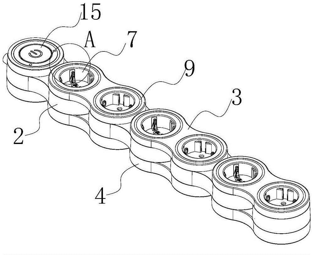
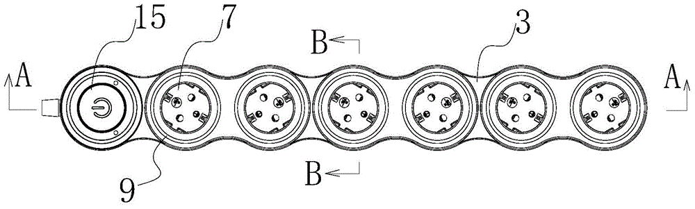
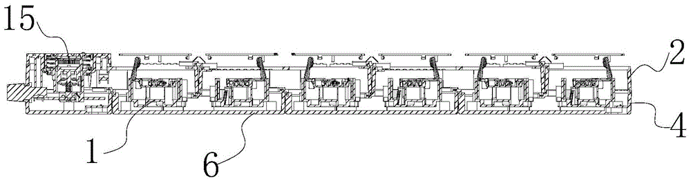
[0031] Such as Figure 1 to Figure 10 As shown, a rotary socket includes a housing and an electrical plug-in core 1 disposed in the housing. The housing includes one or more rotating sleeves 2, socket end caps 3 and bases 4, rotating sleeves 2, and socket end caps. 3 and the base 4 are in the shape of "8"; the end of the housing is provided with a control switch 15 connected to the core body 1 of the electrical plug-in in the rotating sleeve 2.

[0032] There are mounting holes 5 on both sides of the rotating sleeve 2, the socket end cover 3 is arranged above the rotating sleeve 2, the base 4 is arranged below the rotating sleeve 2, the upper and lower positions of the socket end cover 3 and the base 4 are corresponding and connec...


PUM


Abstract

The invention relates to a rotary socket. The rotary socket comprises a casing and electric appliance plug core bodies in the casing, wherein the casing comprises one or more rotary sleeves, socket end caps and bases; mounting end holes are formed in two sides of each rotary sleeve; the socket end caps and the bases are in one-to-one correspondence in the vertical direction and are connected with the mounting end holes of corresponding two adjacent rotary sleeves; core body end caps buckled with the socket end caps are arranged in the mounting end holes in the rotary sleeves; each core body end cap, a bottom plate on the corresponding base and the corresponding mounting end holes define a core body accommodating cavity; the electric appliance plug core bodies are arranged in the core body accommodating cavities and fixedly connected with the bottom plates on the bases, and the electric appliance plug core bodies in the two mounting end holes in the same rotary sleeve are at 60 degrees after being fixed. The rotary socket is similar to a bicycle chain in structure, is good in strength and cannot deform easily; the structure is simple, an insert structure is not required inside, and a jack structure and a rotating structure are integrated; few structural parts are required, so that the assembly process is simple, the assembly efficiency is high, and the cost is low.

Description

technical field [0001] The invention relates to a rotary socket. Background technique [0002] The socket holes of the common power sockets on the market cannot be rotated, which limits the direction of plug insertion, and often causes the insertion direction of the plug to be inconsistent with the direction of the plug lead, which makes the plug lead must be bent before the plug can be inserted. , After long-term use, the lead wire of the plug will fall off or break due to repeated bending. In addition, the plugs of many electrical appliances are installed on the body, such as chargers, timers, etc. These electrical appliances will occupy a large volume on the socket and may interfere with the plugs on other socket holes. For this reason, in order to play a convenient role, a rotatable socket has appeared, for example: 200910008313.0 discloses a rotary socket, including a fixed part and a rotating part body, the fixing part is connected to the body, and the rotating part i...

Claims


Application Information

Patent Timeline
Patent Type & Authority Applications(China)
IPC IPC(8): H01R35/04
CPCH01R35/04
Inventor 王博
Owner 宁波市镇海乌托邦工业设计有限公司
Why Eureka
Try Eureka