
Multiple-input multiple-output antenna transceiver circuit

A transceiver circuit and multi-output technology, applied in electrical components, transmission systems, radio transmission systems, etc., can solve the problem of damage to low-noise amplifiers or radio frequency transceivers, failure of transmit/receive switches to achieve high isolation, and influence on antenna transmit power, etc. question

Inactive Publication Date: 2018-08-07
AMBIT MICROSYSTEMS (SHANGHAI) LTD
View PDF4 Cites 0 Cited by
  • Summary
  • Abstract
  • Description
  • Claims
  • Application Information

AI Technical Summary

Problems solved by technology

[0002] In the multiple-input multiple-output antenna transceiver circuit, a transmit / receive switch is usually set at the receiving end of the antenna to switch between the transmit path and the receive path. Since the transmit / receive switch usually cannot meet the requirements of high isolation, when the radio frequency transceiver When the radio frequency signal to be transmitted to the antenna via the power amplifier, the transmitted radio frequency signal will be coupled to the receiving path and cause damage to the low noise amplifier or radio frequency transceiver. There is also radiation interference between each other, which in turn affects the transmit power of the antenna

Method used


Image

  • Multiple-input multiple-output antenna transceiver circuit
  • Multiple-input multiple-output antenna transceiver circuit
  • Multiple-input multiple-output antenna transceiver circuit

Examples


Embodiment Construction

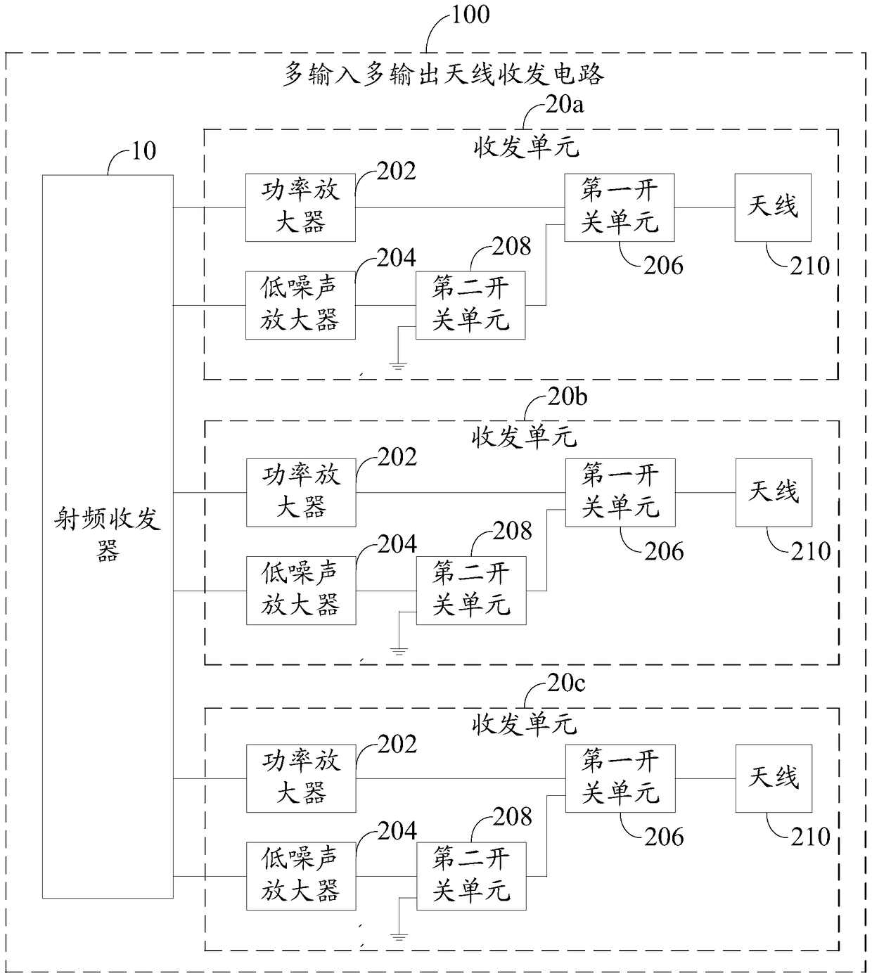
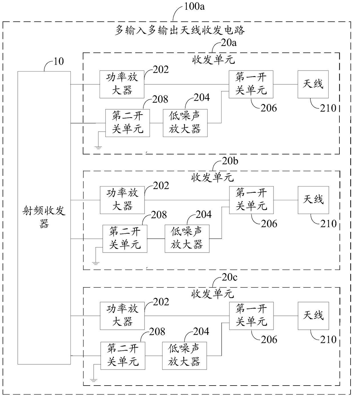
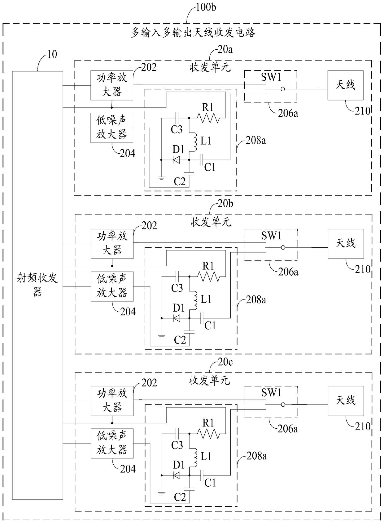
[0030] figure 1 It is a block diagram of the MIMO antenna transceiver circuit 100 in an embodiment of the present invention. In this embodiment, the MIMO antenna transceiver circuit 100 includes a radio frequency transceiver 10 and a plurality of transceiver units 20a, 20b, 20c (in this embodiment, only three are used as an example, but not limited to three , can contain less than or more than three transceiver units) to realize the transmission or reception of multiple signals. Each transceiver unit 20 a , 20 b , 20 c includes a power amplifier 202 , a low noise amplifier 204 , a first switch unit 206 , a second switch unit 208 and an antenna 210 . The power amplifier 202 is electrically connected to the radio frequency transceiver 10 , and the power amplifier 202 amplifies the power of the signal output by the radio frequency transceiver 10 to be transmitted through the antenna 210 . The low noise amplifier 204 is electrically connected to the radio frequency transceiver 1...


PUM


Abstract

A multiple-input multiple-output antenna transceiver circuit includes a radio frequency transceiver and multiple transceiver units, each transceiver unit includes an antenna, a power amplifier, a low-noise amplifier, a first switch unit and a second switch unit. The power amplifier is used to amplify the power of the signal to be transmitted output by the radio frequency transceiver so as to transmit it through the antenna. The low noise amplifier is used to amplify the RF signal received by the antenna and transmit it to the RF transceiver. The first switch unit and the second switch unit are used to select and switch the transceiving path according to the transceiving state of the radio frequency transceiver. The above-mentioned multi-input multi-output antenna transceiver circuit switches the sending and receiving path by adding a switch unit, realizes the isolation of the transmitting path and the receiving path, effectively suppresses the harmonic interference generated between the transmitting path and the receiving path, and improves the performance of adjacent antennas at the same time. isolation between.

Description

technical field [0001] The invention relates to a multiple-input multiple-output antenna transceiver circuit, in particular to a multiple-input multiple-output antenna transceiver circuit that uses switches to increase antenna isolation. Background technique [0002] In the multiple-input multiple-output antenna transceiver circuit, a transmit / receive switch is usually set at the receiving end of the antenna to switch between the transmit path and the receive path. Since the transmit / receive switch usually cannot meet the requirements of high isolation, when the radio frequency transceiver When the radio frequency signal to be transmitted to the antenna via the power amplifier, the transmitted radio frequency signal will be coupled to the receiving path and cause damage to the low noise amplifier or radio frequency transceiver. There is also radiation interference between them, which in turn affects the transmit power of the antenna. Therefore, it has become a major researc...

Claims


Application Information

Patent Timeline
Patent Type & Authority Patents(China)
IPC IPC(8): H04B7/0413H04B1/525
Inventor 郑光伟
Owner AMBIT MICROSYSTEMS (SHANGHAI) LTD
Learn More