Wiper blade with jet separator

A separator and wiper technology, which is applied in vehicle cleaning, vehicle maintenance, transportation and packaging, etc., can solve problems such as delays and achieve efficient cleaning effects

Inactive Publication Date: 2015-09-30
PEZHO SITROEN AUTOMOBILS SA
View PDF6 Cites 2 Cited by
  • Summary
  • Abstract
  • Description
  • Claims
  • Application Information

AI Technical Summary

Problems solved by technology

[0009] One of the drawbacks of these wipers is that there is a delay between the first and second steps to allow the fluid to be evenly distributed along the lip

Method used


Image

  • Wiper blade with jet separator
  • Wiper blade with jet separator
  • Wiper blade with jet separator

Examples


Embodiment Construction

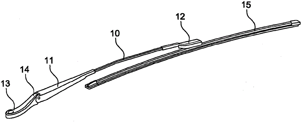
[0030] figure 1 A shaft 10 and a wiper wiper 15 according to the invention are shown. The rod body 10 includes a housing 11 at one of its two ends and a coupling cover 12 at the other end. The housing 11 is connected to the driver 13 via a hinge 14 . The driver 13 is connected with a motor (not shown), ensuring the rotary reciprocating motion of the wiper.

[0031] The coupling cover 12 connects the rod body 10 to the wiping wiper 15 , so that the wiper wiper 15 can rotate relative to the rod body 10 along the axis perpendicular to the rod body 10 at the coupling cover 12 .

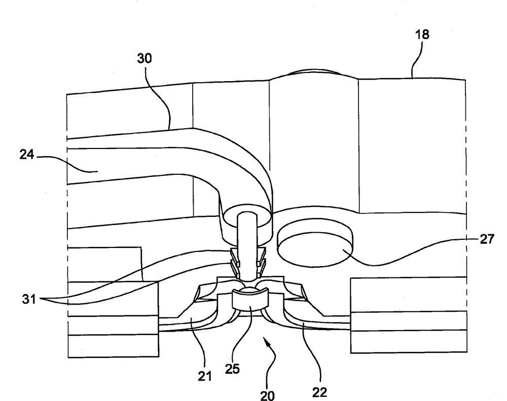
[0032] The windshield wiper 15 according to the invention comprises an injection opening from which the jet jet is divided into a plurality of jet streams by a separator. Each jet is directed towards a portion of the wiper blade 17 (or wiper sheet) by the separator.

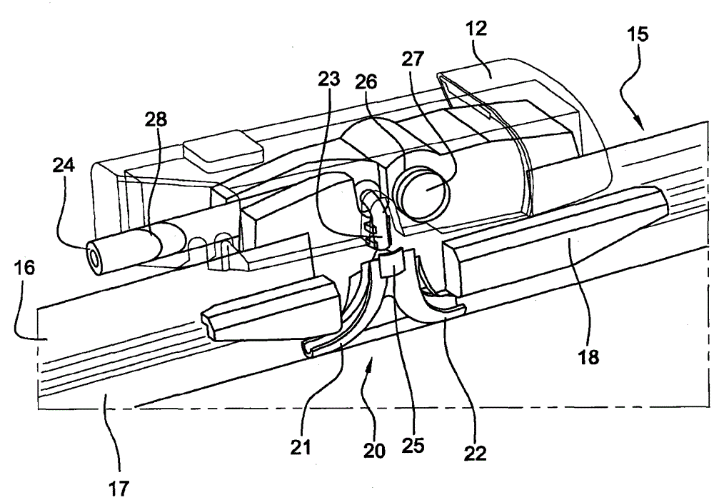
[0033] refer to figure 2 , 3 and 4, the wiping wiper 15 includes a deflector 16 , a wiping sheet 17 and an adapter 18 . The deflect...


PUM


Abstract

The invention concerns a wiper blade (15) for a glazed panel comprising a flexible strip (17) and a system for spraying washing liquid, comprising a spray port (23) for spraying washing liquid, and a separator comprising first (21) and second (22) guide means, said spray port (23) being oriented so as to spray the washing liquid towards the separator, said guide means (21, 22) being disposed such that the sprayed washing liquid spreads over a concave portion formed by the strip (17) when the blade (15) is in an idle position, the first (21) and the second (22) means for guiding washing liquid being oriented respectively towards a first end and a second end of the blade (15).

Description

technical field [0001] The present invention relates to the wiping of glass panels, and more particularly to wiper wiper blades. Background technique [0002] Traditional windshield wipers usually include a rod body controlled by a reversible drive motor to rotate reciprocally. The rod body supports a flexible wiper blade (also called a sheet) made of rubber or similar materials. Between the rods of the balance bar system, the wiper blade rests against the surface of the windshield, and the balance rod system can be deformed in the area where the wiper blade is pressed tightly according to the angular position of the rods and the curvature of the windshield. [0003] Washing of the windscreen or the rear window is usually carried out by spraying a washer fluid onto the glass surface by means of nozzles which are arranged on the vehicle bonnet or the vehicle ventilation grille. Said nozzles, which are placed at a distance from the glass surface to be cleaned, are difficult t...

Claims


Application Information

Patent Timeline
Patent Type & Authority Applications(China)
IPC IPC(8): B60S1/38B60S1/52
CPCB60S1/524B60S1/3862
Inventor F·吉代G·热弗N·里拉特
Owner PEZHO SITROEN AUTOMOBILS SA
Why Eureka
Try Eureka