Clamping mechanism and tractor applying clamping mechanism

A clamping mechanism and tractor technology, applied in the tractor field, can solve the problems of easily damaged profile surface, time waste, etc.

Active Publication Date: 2015-10-07
佛山市腾和机械制造有限公司
View PDF5 Cites 4 Cited by
  • Summary
  • Abstract
  • Description
  • Claims
  • Application Information

AI Technical Summary

Problems solved by technology

Waste of time as the push rod has to travel a distance to reach the profile
Because the pu

Method used


Image

  • Clamping mechanism and tractor applying clamping mechanism
  • Clamping mechanism and tractor applying clamping mechanism
  • Clamping mechanism and tractor applying clamping mechanism

Examples


Embodiment a1

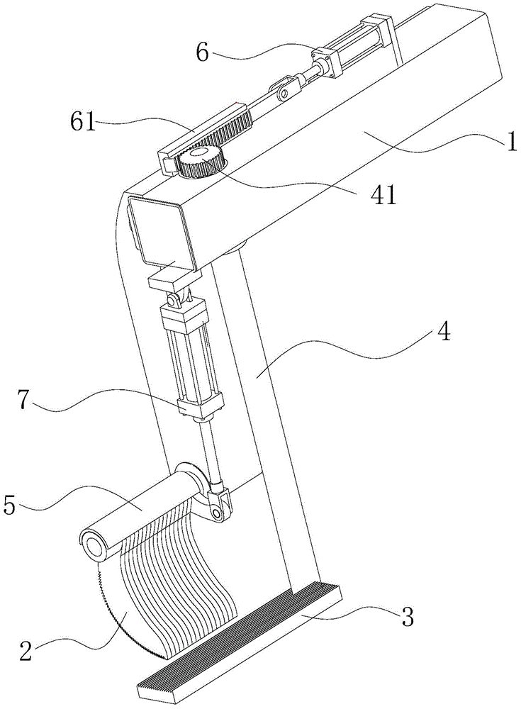
[0024] Embodiment a1: with reference to figure 1 , is an embodiment of the clamping mechanism of the present invention.

Embodiment a2

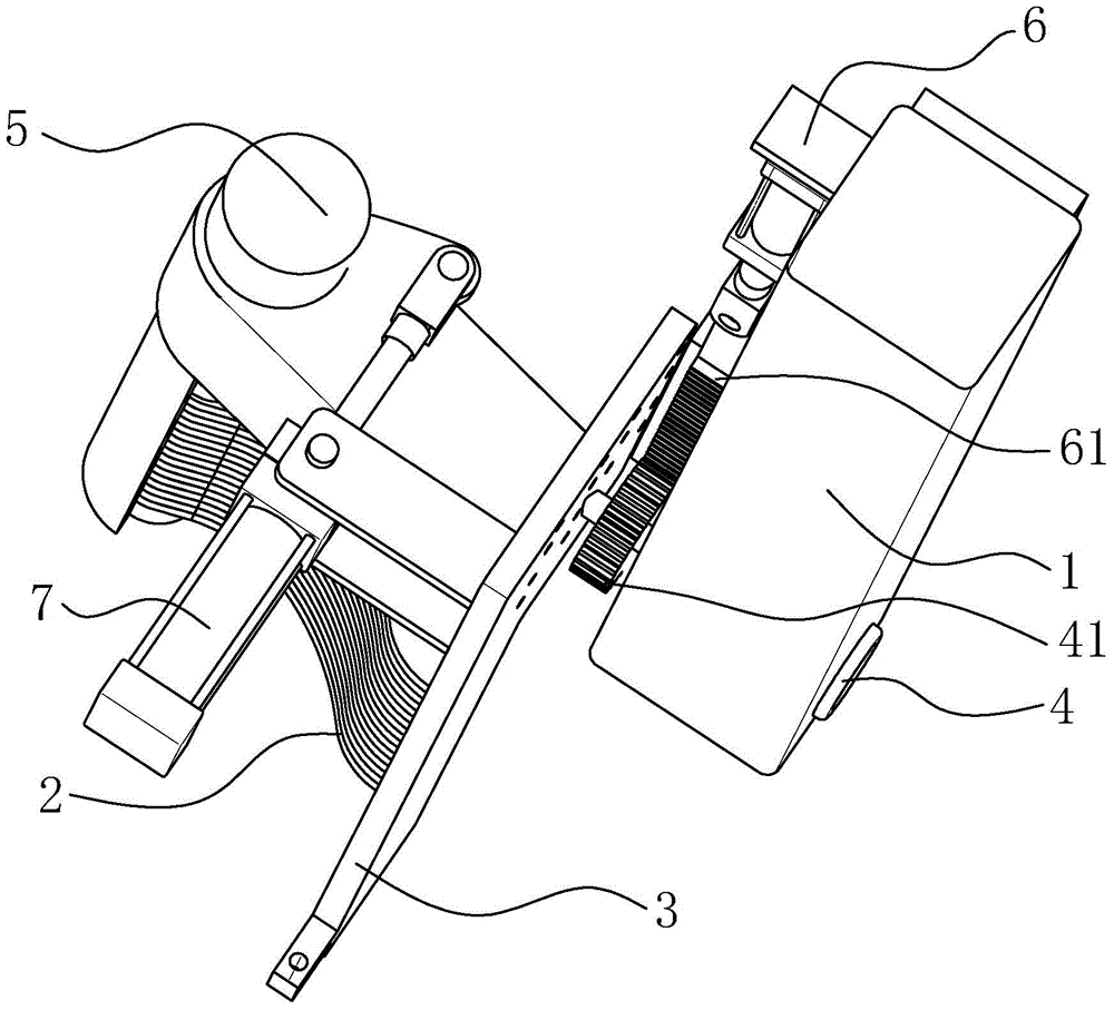
[0025] Embodiment a2: with reference to figure 2 , is another embodiment of the clamping mechanism of the present invention.

[0026] Embodiment a1 and embodiment a2 have the same connection and driving relationship of their components, and their working principles are also the same, as follows:

[0027] The clamping mechanism includes a base frame assembly 1 and a clamping assembly. The base frame assembly 1 is provided with a longitudinally extending longitudinal axis assembly 4 and a transversely extending horizontal axis assembly 5; the clamping assembly includes an upper The claw assembly and the supporting plate 3; the supporting plate 3 that can rotate around the axis of the longitudinal axis assembly 4 is connected with the vertical axis assembly 4, and the upper claw assembly that can rotate around the axis of the horizontal axis assembly 5 is connected with the horizontal axis assembly 5; The longitudinal axis assembly 4 is connected with the longitudinal axis driv...

Embodiment a3

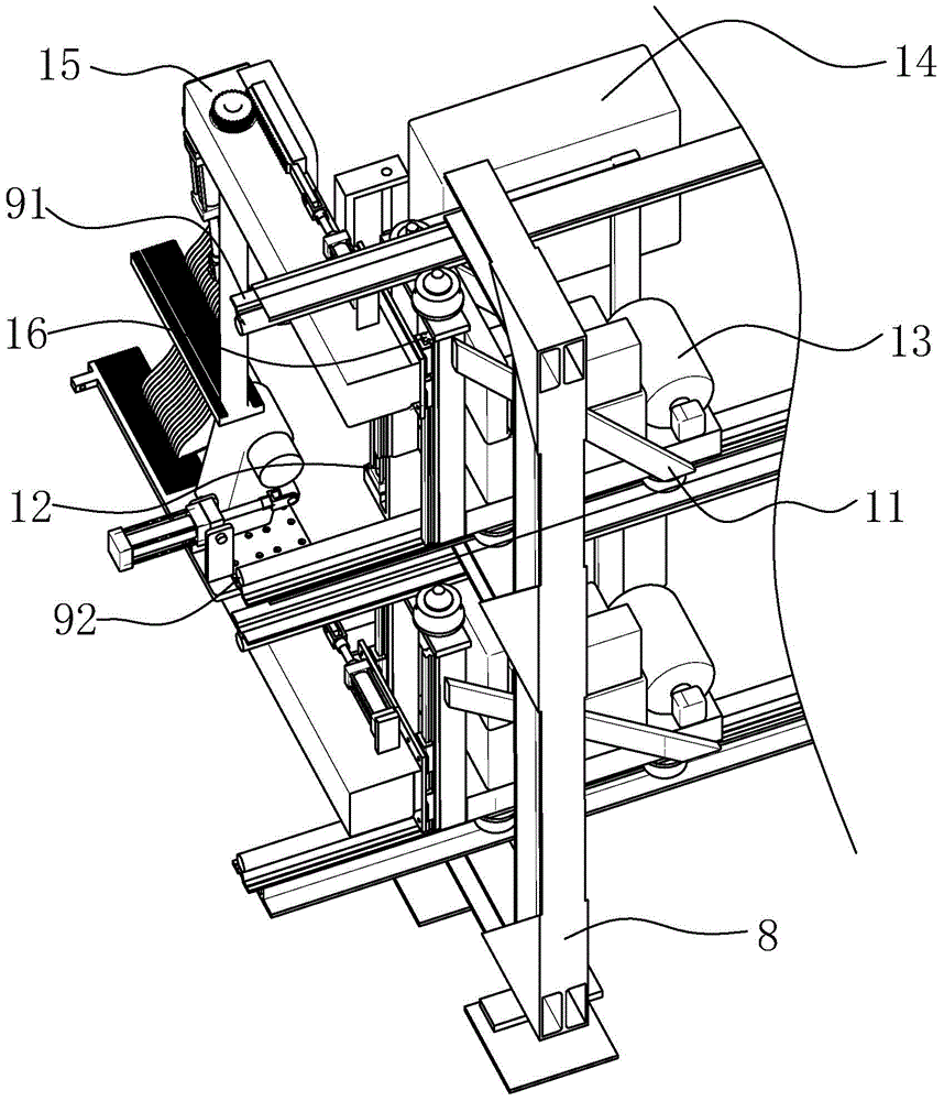
[0031] Embodiment a3: with reference to image 3 and Figure 4 , a traction machine, including a frame 8 and a clamping unit arranged on the frame 8, the clamping unit includes a guide rail group, a connecting frame 11, and a clamping mechanism; the frame 8 is provided with a guide rail group extending forward and backward The connecting frame 11 that moves back and forth on the guide rail group is provided with a clamping mechanism; the described guide rail group is provided with an upper guide rail 91 and a lower guide rail 92 connected with the connecting frame 11 from top to bottom, and the connecting frame is provided with a guide rail The sliding roller assembly on the set enables the connecting frame 11 to move smoothly and quickly on the guide rail set.

[0032] Furthermore, the sections of different profiles are large and small, in order to adapt to different profiles; at the same time, after a longer profile is pulled out for a longer distance, there will be a large...


PUM


Abstract

The invention discloses a clamping mechanism. The clamping mechanism comprises a base frame component and a clamping component, wherein the base frame component is provided with a longitudinal shaft component longitudinally extending and a transverse shaft component transversely extending; the clamping component comprises an upper jaw component and a support plate; the support plate is connected with the longitudinal shaft component, and rotates around the axis thereof; the upper jaw component is connected with the transverse shaft component, and rotates around the axis thereof; the longitudinal shaft component is connected with a longitudinal shaft driving component; the upper jaw component is connected with a transverse shaft driving component; and the longitudinal shaft driving component and the transverse shaft driving component are arranged on the base frame component. The transverse shaft driving component drives the upper jaw component to upwards rotate to release a profile in unloading; then, the longitudinal shaft driving component enables the support plate to rotate by a certain angle to leave from the bottom end of the profile; and the profile automatically drops down due to gravity, so that the time is saved, and the profile is not damaged. A tractor provided with the clamping mechanism can quickly tow the profile, and can quickly unload while undamaging the profile. The clamping mechanism and the tractor are used for large-span profiles, in particular for the clamping and quick traction of aluminum profiles.

Description

technical field [0001] The invention relates to a clamping mechanism and a pulling machine using the clamping mechanism, which is used for the production of long strip profiles, especially the production of aluminum profiles. Background technique [0002] In the profile extrusion process, in order to reduce bending and twisting and improve the qualified rate of finished products, the profile must be clamped and pulled. The existing profile double tractors are generally used for large-scale aluminum profiles and large-scale production. The body is heavy and the traction force is large, but for the production of small material profiles, the weight of the machine body consumes a lot of energy, and its inertia is large during the traction process, and the movement is not flexible. It is not suitable for small materials, a die with multiple holes and fast extrusion Profile production field. However, the existing tractors with upper and lower clamping units rely on push rods to c...

Claims


Application Information

Patent Timeline
IPC IPC(8): B21C1/32
CPCB21C1/32
Inventor 张传来
Owner 佛山市腾和机械制造有限公司
Why Eureka
Try Eureka