
Multi-spray-head interference-free printing method and spray head structure of 3D printer

A 3D printer, non-interference technology, applied in printing and other directions, can solve the problems of increasing failure rate, increasing printer volume, interference, etc.

Inactive Publication Date: 2015-10-07
北京威控睿博科技有限公司
View PDF7 Cites 16 Cited by
  • Summary
  • Abstract
  • Description
  • Claims
  • Application Information

AI Technical Summary

Problems solved by technology

In this way, when printing, the standby nozzle will easily scratch the printing object or cause interference to other nozzles, reducing the printing quality
In order to make up for this defect, some printers fixedly increase the distance between the nozzles, so that the standby nozzles are horizontally away from the printing object, but this method increases the volume of the printer, increases the switching time of the nozzles, reduces printing efficiency, and increases the cost of the printer. Application The range is small, and the number of prints of the printer is limited at the same time
The patent with the publication number CN104608381 discloses a method of adjusting the height of the nozzles. Although this method realizes the avoidance of scratching and interference between the nozzles and the printing object, the specification of the patent only discloses a technical solution for the linkage of two nozzles, while three One or more multi-nozzles obviously cannot adopt the technical scheme of the patent specification
At the same time, in this patented technical solution, each nozzle needs to be moved up and down. The original structure of the nozzle needs to be redesigned, and the feeding pipe needs to be redesigned. The distance is determined by multiple parts such as springs, racks, cross bars, and supports. The structure is too complicated, which increases the failure rate and reduces its accuracy.

Method used


Image

  • Multi-spray-head interference-free printing method and spray head structure of 3D printer
  • Multi-spray-head interference-free printing method and spray head structure of 3D printer
  • Multi-spray-head interference-free printing method and spray head structure of 3D printer

Examples


Embodiment Construction

[0018] The present invention will be further described below in conjunction with the accompanying drawings.

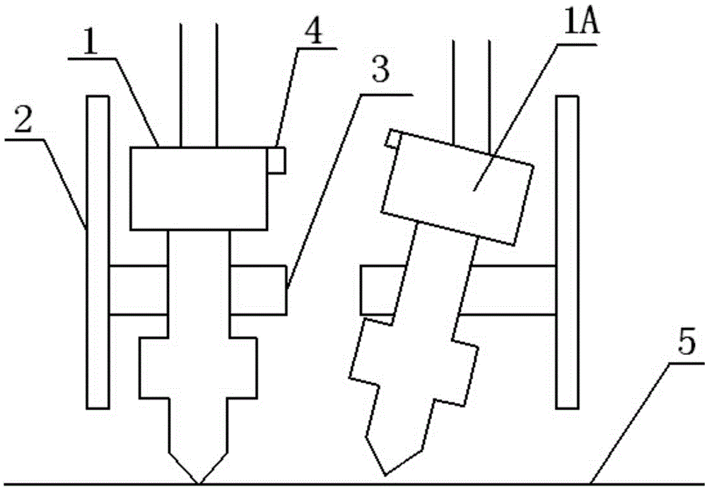
[0019] combine figure 1 , a 3D printer multi-nozzle non-interference printing method, a tilting device is provided for each nozzle, and the non-working nozzle is tilted during printing so that the top nozzle is separated from the working plane, and only the nozzle of the working nozzle is at the working height. After the nozzle is tilted, the nozzle is 0.4-0.8mm away from the working plane after the nozzle is tilted. In the figure, the spray head 1 is in the working state, and the spray head 1A is a spray head that is tilted away from the working plane 5 .

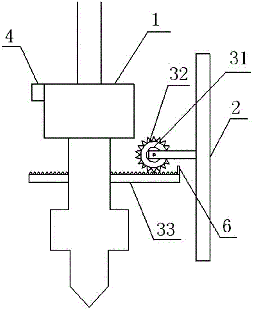
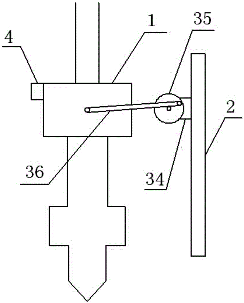
[0020] Such as figure 1 As shown, a 3D printer nozzle structure adopting the above-mentioned non-interference printing method includes a nozzle 1, a guard plate 2, and a tilting device 3 connected to the nozzle and the guard plate respectively. In this embodiment, the tilting device includes a driving assembly f...


PUM


Abstract

The invention discloses a multi-spray-head interference-free printing method of a 3D printer, which is characterized in that each spray head is provided with a tilting device, the spray heads, which are not in operation, are tilted in printing, a spray nozzle of each spray head, which is not in operation, is enabled to break away from an operating plane, and only the spray nozzles of the spray heads, which are in operation, are located at the operating height. In the technical scheme disclosed by the invention, each spray head can be tilted independently and does not affect other spray heads, a spray head material conveying pipe is a flexible pipe, small-angle tilt of the spray head basically has no influence on the material conveying pipe, the spray heads are slightly modified, the structure is simple, and the cost is reduced. Meanwhile, an upper endpoint of each spray head is fixed in position, the spray nozzle moves in a circular arc mode, and tilt and recovery of the spray head have no influence on the precision.

Description

technical field [0001] The invention belongs to the field of 3D printing technical equipment, and in particular relates to a multi-nozzle non-interference printing method of a 3D printer and a nozzle structure thereof. Background technique [0002] At present, in 3D printing technology, there are more and more ways to print with multi-nozzles. When printing some products, due to the different materials or colors of the products, multi-nozzles are often used to print together. At present, the printing nozzles of 3D printers are generally on the same working plane, and only one nozzle works alone during printing, but the rest of the standby nozzles will also move in parallel with this nozzle. In this way, when printing, the standby nozzle will easily scratch the printing object or cause interference to other nozzles, reducing the printing quality. In order to make up for this defect, some printers fixedly increase the distance between the nozzles, so that the standby nozzles ...

Claims


Application Information

Patent Timeline
Patent Type & Authority Applications(China)
IPC IPC(8): B41J2/01
Inventor 张海涛
Owner 北京威控睿博科技有限公司
Learn More