

Cylinder suction cup machine and gantry frame type cantilever suction cup machine
A cylindrical suction cup machine, suction cup machine technology, applied in the direction of conveyor objects, furnaces, lighting and heating equipment, etc., can solve the problems of single-arm guide rails that are easy to twist, hurt personal safety, and will tilt
- Summary
- Abstract
- Description
- Claims
- Application Information
AI Technical Summary
Problems solved by technology
Method used
Image

Examples
Embodiment Construction
[0023] The present invention will be further described below in conjunction with the accompanying drawings.
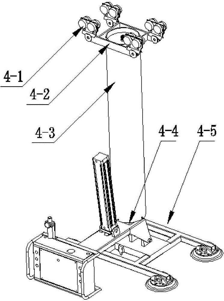
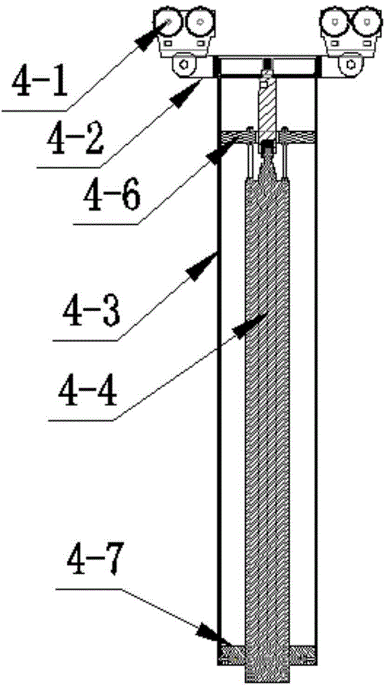
[0024] Such as figure 1 and figure 2 As shown, a cylindrical suction cup machine includes a track trolley 4-1, a cylindrical support 4-2, a circular steel cylinder 4-3, a vertical lifting cylinder 4-4, a suction cup support 4-5, and a cylinder guiding sliding disc 4-6, cylinder fixed disc 4-7;
[0025] The shaft of the vertical lift cylinder 4-4 is fixed with the cylinder support 4-2 by a plane bearing, and the shell of the vertical lift cylinder 4-4 is fixed on the cylinder guiding slide disk 4-6, and the shell of the vertical lift cylinder 4-4 Sliding with the cylinder guide sliding disc 4-6 to reach the elongation and contraction of the vertical lift cylinder 4-4, the fixed disc 4-7 of the cylinder is fixed with the circular steel cylinder 4-3 with bolts, and is connected with the vertical lift cylinder 4-4. The shell of 4 maintains a gap of 0.3 ~ 0.5mm for the ...
PUM
 Abstract
Description
Claims
Application Information