Roller device of computerized flat knitting machine

A computerized flat knitting machine and roller technology, which is applied in textiles and papermaking, weft knitting, knitting, etc., can solve the problems of limiting the lifting space of the bottom plate, prone to incomplete opening, and difficulty in ensuring meshing accuracy, etc., to reduce wear and tear, The effect of compact structure and guaranteed precision

Active Publication Date: 2015-10-07
浙江万事兴机械有限公司
View PDF6 Cites 2 Cited by
  • Summary
  • Abstract
  • Description
  • Claims
  • Application Information

AI Technical Summary

Problems solved by technology

This type of roller has the following defects: 1. After the active roller and the passive roller are opened, they lose power and cannot rotate, and cannot pull the fabric, and it is difficult to adjust the traction force by changing the distance between the active and passive rollers; 2. The active roller and the passive roller When opening, the two transmission gears for motion transmission are also opened, and it is difficult to ensure the meshing accuracy when closing again, which is easy to cause gear wear; 3. The driving roller and passive roller are prone to incomplete opening during use, which limits The rising space of the bottom plate is easy to collide with the active roller, which will affect the service life

Method used


Image

  • Roller device of computerized flat knitting machine
  • Roller device of computerized flat knitting machine
  • Roller device of computerized flat knitting machine

Examples


Embodiment Construction

[0029] The present invention will be further described below in conjunction with the accompanying drawings, but the present invention is not limited to the following examples.

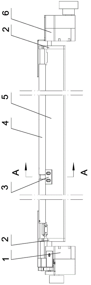
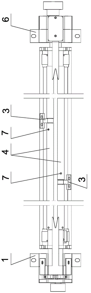
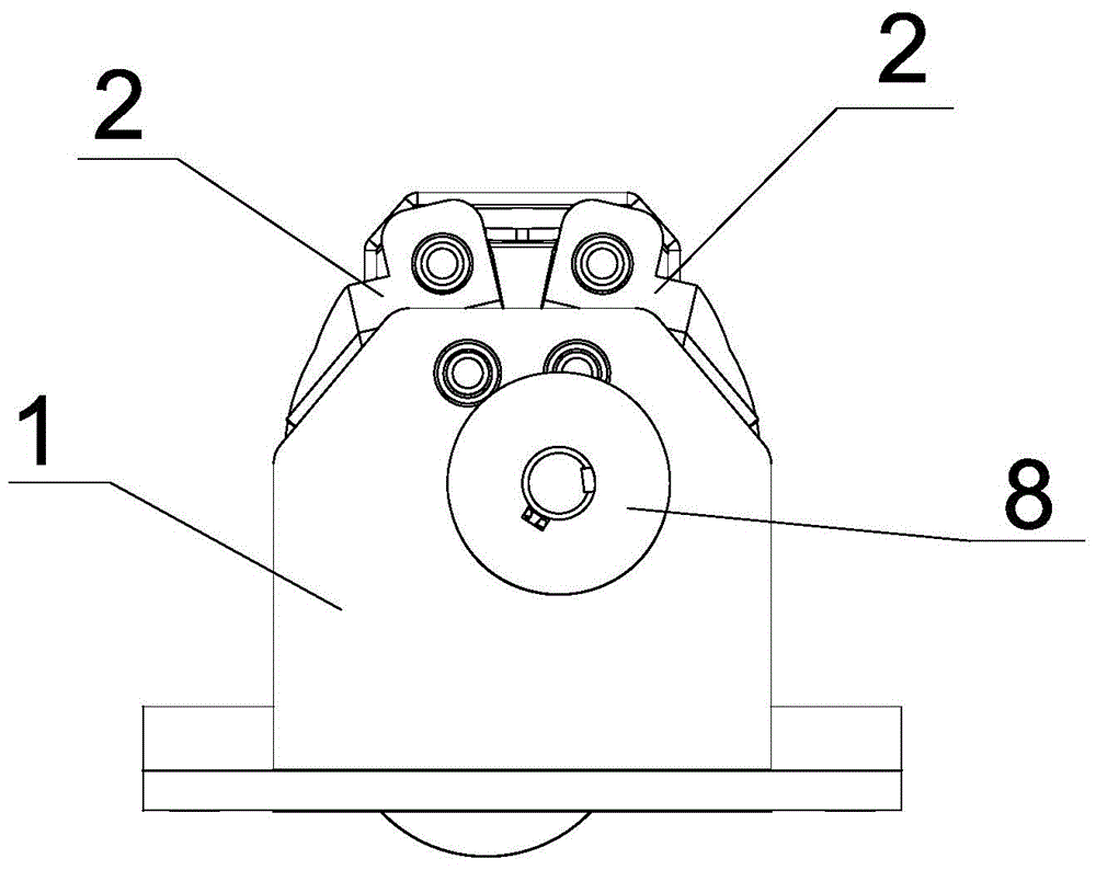
[0030] Such as figure 1 , 2 , 7, and 8, the roller device of a computerized flat knitting machine according to the present invention includes a left bracket 1, a right bracket 6 and two rollers 4 (it is recommended to use iron rollers, and rollers of other materials can also be used. can be determined according to needs), the roller surface can be corrugated or cylindrical shape, can be determined according to needs. The left bracket and the right bracket are respectively fixed on the machine tool, and the left end and the right end of each roller are rotatably positioned on the left and right brackets respectively through the swing block 2, and the swing blocks at the left and right ends of each roller pass through the rigid bar 5 ( It is recommended to use aluminum rods, but also can use material r...


PUM


Abstract

The invention relates to a roller device of a computerized flat knitting machine and aims to tract fabric by two rollers of the device after the two rollers are open and can still rotate. Traction force can be adjusted via adjustments of a gap between the two rollers; and when the rollers open and close, transmission gear engaging precision can be guaranteed, so transmission gear abrasion can be reduced, interference to a base plate can be avoided and service life of the transmission gear can be prolonged. The technical scheme is that the roller device of the computerized flat knitting machine comprises a left carrying rack, a right carrying rack and two rollers. The roller device is characterized in that the left and right ends of each roller are rotationally positioned on the left and right carrying rack individually via two swinging blocks; a driving assembly driving the two rollers to rotate is installed on the left carrying rack; and an opening-closing assembly driving the two swinging blocks to swing to enable the two rollers to close and open is installed on the right carrying rack.

Description

technical field [0001] The invention relates to the technical field of flat knitting machines, in particular to a roller device of a computerized flat knitting machine. Background technique [0002] The pulling mechanism is an important part of the computerized flat knitting machine. Its function is to generate an appropriate pull-down force on the old coil to overcome the resistance generated by the knitting needle when it is withdrawing and looping, assist in the completion of the knitting action, and turn the looped The fabric is led away from the needle bed. The pulling mechanism mainly includes a roller and a sinker. When working, the sinker presses down the coil, and the roller pulls the fabric. Since there is a distance between the roller and the knitting mouth of the needle bed, a lifter can be added if necessary. After the lifter is raised, the knitted fabric just woven is pulled down to the position where the roller can pull. , the roller must be fully opened to ...

Claims


Application Information

Patent Timeline
IPC IPC(8): D04B15/90
Inventor 陈亚江
Owner 浙江万事兴机械有限公司
Why Eureka
Try Eureka