
Refrigerating device

A technology of refrigeration equipment and airbags, which is applied to household refrigeration equipment, lighting and heating equipment, cooling fluid circulation devices, etc., can solve the problems of small overall thickness, large deformation, and large number of door seal airbags, etc., to reduce the heat exchange area, Good sealing effect, reducing the effect of heat transfer and cooling loss

Inactive Publication Date: 2015-10-07
HISENSE RONSHEN GUANGDONG FREEZER
View PDF5 Cites 8 Cited by
  • Summary
  • Abstract
  • Description
  • Claims
  • Application Information

AI Technical Summary

Problems solved by technology

[0003] In order to overcome at least one of the above-mentioned defects in the prior art, the present invention provides a refrigeration equipment, which has a large number of door seal airbags, large deformation when pressed, and good sealing effect, which can reduce the energy consumption of the refrigeration equipment and reduce the The door seal is condensed, and the overall thickness of the door seal is small when it is under pressure, so the overall volume of the refrigeration equipment can be reduced when the volume of the refrigeration equipment remains unchanged

Method used


Image

  • Refrigerating device
  • Refrigerating device
  • Refrigerating device

Examples


Embodiment 1

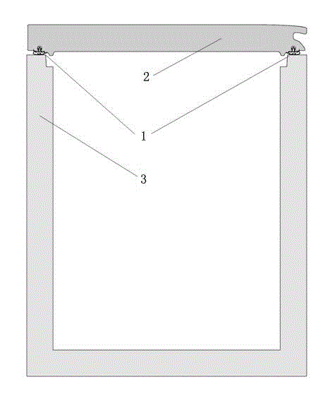
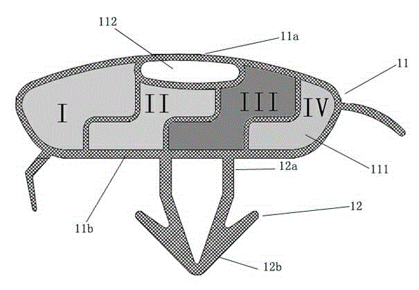
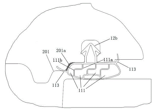
[0024] Such as figure 1 It is a structural schematic diagram of a refrigeration device of the present invention, which includes a box body 3 , a door body 2 and a door seal 1 . figure 2 The door seal 1 is shown, and the door seal 1 includes a first part 11 and a second part 12, wherein: the first part 11 includes several connected airbags 111, and the airbag walls connected to the airbags 111 are "ㄣ"-shaped structures, and An accommodating cavity 112 for accommodating the magnetic strip is provided, and the accommodating cavity 112 is connected with the airbag 111 and located on a side close to the first end surface 11 a of the first part 11 . combine figure 2 , when the door seal 1 is pressed, the first end surface 11a of the first part 11 is in close contact with the box body 3; the first end 12a of the second part 12 is connected with the second end surface 11b of the first part 11, and the second The two ends are provided with hooks 12b, which are used to engage in th...

Embodiment 2

[0030] Such as Figure 5 As shown, in this embodiment, the airbag wall connected to the airbag 111 is a "ㄑ"-shaped structure. Since the "ㄑ"-shaped structure has better stretchability, the airbag 111 has greater compression in the opening and closing direction of the door body 2 when it is pressurized. amount, so that the gas in the airbag 111 is squeezed in a direction perpendicular to the opening and closing direction of the door body 2, and finally the airbag 111 is stretched in a direction perpendicular to the opening and closing direction of the door body 2. The first end surface 11a and the second end surface of the door seal 1 11b is stretched while the airbag 111 is stretched, so as to increase the contact area between the door seal 1 and the door body 2 and the box body 3 to achieve a better sealing effect. Other structures of this embodiment are the same as those of Embodiment 1, and will not be repeated here.


PUM


Abstract

The invention discloses a refrigerating device which comprises a box body (3), a door body (2) and a door gasket (1). The refrigerating device is characterized in that the door gasket (1) comprises a first part (11) and a second part (12), the first part (11) comprises a plurality of connected air bags (111), the connected walls of the air bags are each of a telescopic wrinkle structure, and when the door gasket (1) is pressed, a first end face (11a) of the first part (11) is tightly attached to the box body (3); a first end (12a) of the second part (12) is connected with a second end face (11b) of the first part (11), and a second end is provided with a hook (12b) which is used for being clamped in a door groove, matched with the hook, in the door body (2) so as to be fixedly connected with the door body (2). The door gasket is simple in structure, sealing performance is good, the thickness is small when the refrigerating device is pressed, and quite high market competitiveness is achieved.

Description

technical field [0001] The invention relates to the technical field of refrigeration equipment, in particular to refrigeration equipment. Background technique [0002] At present, the door seals of refrigeration equipment on the market have less door seal airbags and insufficient elasticity when under pressure, and the airbag walls connected between the airbags are generally straight walls, and the deformation of the airbag walls is small when under pressure, making the door seal and the door body The lack of tight fit with the box body results in poor sealing effect, which increases the amount of cooling leakage and increases the energy consumption of the refrigeration equipment. In addition, the overall thickness of the door seal is large, so the overall volume of the refrigeration equipment is increased, resulting in packaging and transportation. Contents of the invention [0003] In order to overcome at least one of the above-mentioned defects in the prior art, the pr...

Claims


Application Information

Patent Timeline
IPC IPC(8): F25D23/02
CPCF25D23/028F25D2323/02
Inventor 黄鹏昌程凯许粤海陈国良曾东
Owner HISENSE RONSHEN GUANGDONG FREEZER
Learn More