A kind of driving and loading device, method and application of kc test bench

A loading device and test bench technology, which is used in measuring devices, vehicle testing, and machine/structural component testing. and amplifying, reducing motion load, and the effect of good dynamic performance

Active Publication Date: 2016-06-01
HUAZHONG UNIV OF SCI & TECH
View PDF5 Cites 0 Cited by
  • Summary
  • Abstract
  • Description
  • Claims
  • Application Information

AI Technical Summary

Problems solved by technology

However, the above two driving and loading methods have obvious defects in realizing the small displacement rotation of the Rz axis to measure the force and moment. In the first method, when the disk rotates, the direction of the force is not completely consistent with the direction of the disk. tangent, so the measured righting torque is not particularly accurate; in another way, the lubrication is complicated, the transmission efficiency is low, and a torque sensor is required to directly measure the applied righting torque, which is costly

Method used


Image

  • A kind of driving and loading device, method and application of kc test bench
  • A kind of driving and loading device, method and application of kc test bench
  • A kind of driving and loading device, method and application of kc test bench

Examples


Embodiment Construction

[0034]In order to make the object, technical solution and advantages of the present invention clearer, the present invention will be further described in detail below in conjunction with the accompanying drawings and embodiments. It should be understood that the specific embodiments described here are only used to explain the present invention, not to limit the present invention. In addition, the technical features involved in the various embodiments of the present invention described below can be combined with each other as long as they do not constitute a conflict with each other.

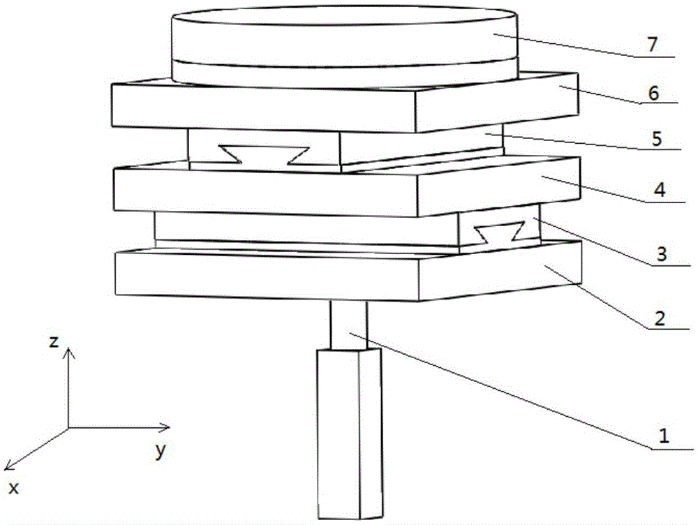
[0035] The driving and loading platform constructed according to a preferred embodiment of the present invention can realize coordinated control of driving displacement using three linear driving systems in the same plane, and realize 3-RPR driving and loading of the KC test bench plane.

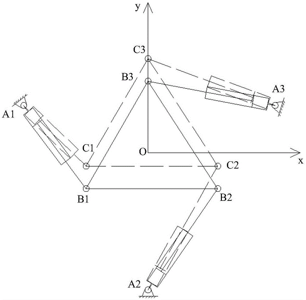
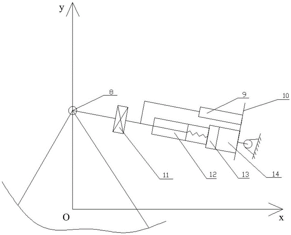
[0036] figure 2 It is a schematic structural diagram of the planar 3-RPR parallel drive loading method ado...


PUM


Abstract

The invention discloses a KC test stand driving loading device comprising a vertical motion platform which is connected with a vertical driving mechanism and can be driven and loaded by the vertical driving mechanism to realize vertical motion, and a longitudinal, lateral and rotary motion driving platform which is arranged on the vertical motion platform. The longitudinal, lateral and rotary motion driving platform is respectively hinged with the power output members of three linear motion driving mechanisms via three driving connection points which are triangularly arranged on the longitudinal, lateral and rotary motion driving platform. The longitudinal, lateral and rotary motion driving platform is driven to perform translational motion along an x-axis and y-axis or rotary motion around a z-axis on the plane via linkage driving control of the three linear motion driving mechanisms. The invention also discloses a corresponding driving loading method and an application thereof. Accurate loading of a KC test stand can be realized so that error is low, motor power in a driving single-axis direction is relatively low, and more importantly, high-efficiency and accurate transmission can be realized in rotary loading and acting force and moment measurement is simple and accurate.

Description

technical field [0001] The invention belongs to the technical field of KC test of vehicle chassis system, and in particular relates to a driving and loading device, method and application of a KC test bench. Background technique [0002] The KC test of the vehicle chassis system mainly includes parallel wheel jump, reverse wheel jump, longitudinal force loading, lateral force loading, aligning moment loading and in-situ steering conditions. Each tire has vertical (z-direction), longitudinal (x-direction), lateral (y-direction) and rotational (Rz-direction) drive loading functions around the vertical direction. The vehicle coordinate system is adopted, that is, when the vehicle is in a stationary state on a horizontal road, the z-axis of the coordinate system is defined to point upward through the center of mass of the vehicle, the x-axis is parallel to the ground and points to the rear of the vehicle, and the y-axis is the direction of the driver pointing to the co-pilot. ...

Claims


Application Information

Patent Timeline
Patent Type & Authority Patents(China)
IPC IPC(8): G01M17/007
Inventor 祝恒佳张云清周红军刘向
Owner HUAZHONG UNIV OF SCI & TECH
Why Eureka
Try Eureka