Single-sided square indexable cutting inserts and cutting tools

A technology for cutting inserts and cutting tools, which is applied to cutting blades, tools for lathes, forming knives, etc., and can solve problems such as unacceptable and invalid joints

Active Publication Date: 2017-08-25
ISCAR LTD
View PDF2 Cites 0 Cited by
  • Summary
  • Abstract
  • Description
  • Claims
  • Application Information

AI Technical Summary

Problems solved by technology

[0005] It is envisaged that an alternative square indexable cutting insert from US 7,387,474, with four sets of concave type engagement portions and four indexing positions, would result in an unacceptably short elongated slots and invalid joints of

Method used


Image

  • Single-sided square indexable cutting inserts and cutting tools
  • Single-sided square indexable cutting inserts and cutting tools
  • Single-sided square indexable cutting inserts and cutting tools

Examples


Embodiment Construction

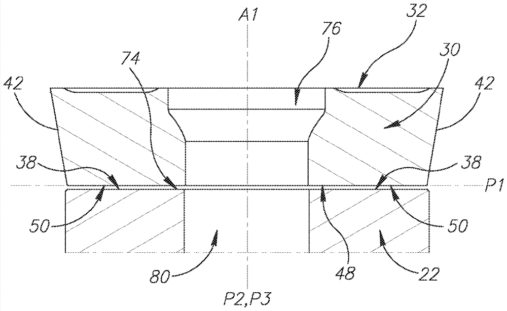
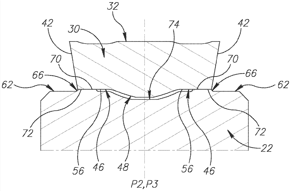
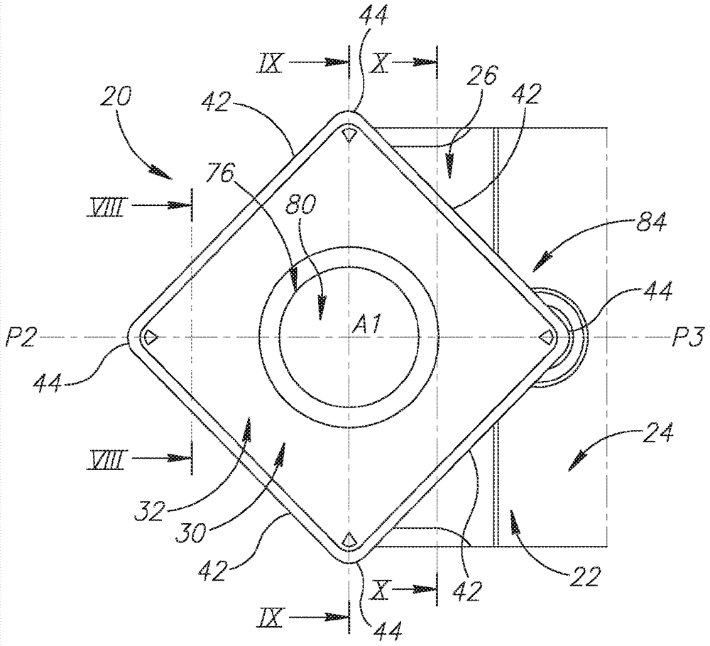
[0044] The present invention relates to a cutting tool 20 comprising a tool holder 22 having a main body 24 with an insert receiving pocket 26 formed at a front end 28 thereof and a single-sided indexable cutting insert 30 . A single-sided indexable cutting insert 30 is removably secured in the insert receiving pocket 26 .

[0045] In some embodiments of the present invention, such as figure 1 and 2 As shown, the cutting tool 20 may be in the form of a turning tool having a holder shank 82 extending away from the front end 28 of the body 24 .

[0046] Also, in some embodiments of the invention, the tool holder 22 may be made of machined steel and the cutting insert 30 is preferably made by forming and sintering cemented carbide (eg, tungsten carbide), And can be coated or uncoated.

[0047] According to the present invention, if image 3 and Figure 4 As shown in , the cutting insert 30 has opposing square upper and lower surfaces 32, 34 and a peripheral side surface 36 e...


PUM


Abstract

A cutting tool (20) comprising: a tool holder (22) having a body (24) having an insert receiving pocket (26) formed at a front end (28) thereof and a removable The single-sided square indexable cutting insert (30) is fixed in the insert receiving pocket (26); the insert receiving pocket (26) includes: a seating surface (60) having a plate surface ( 62) having a single engagement groove (64) recessed therein and two separate support pads (66) protruding therefrom; said engagement groove (64) comprising a pair of parallel an extended groove side surface (68) forming a V-shaped cross-section, and each of said two support pads (66) has a raised support surface (70), wherein said two support surfaces (70) share surface, and the cutting insert (30) includes: opposing square upper and lower surfaces (32, 34) and a peripheral side surface (36) extending therebetween, the peripheral side surface (36) having four four corner surfaces (40) alternating with a rear surface (42); through the central axis (A1) of said upper and lower surfaces (32, 34), said cutting insert (30) can ) index; and a corner cutting edge (44) formed at the intersection of the upper surface (32) and each of the four corner surfaces (40), the lower surface (34) including a base surface ( 46) and having precisely four engaging ridges (50) protruding from said base surface (46), wherein each engaging ridge (50) comprises a pair of parallel extending ridge side surfaces forming a V-shaped section ( 54), and each of said engaging ridges (50) intersects one of said four corner surfaces (40) and extends therefrom towards said central axis (A1), wherein said cutting insert (30) The lower surface (34) of the insert receiving pocket (26) is clamped against the seating surface (60) by: the engagement ridge (50) positioned closest to the operative corner cutting edge (44) the pair of ridge side surfaces (54), which are in contact with the corresponding pair of groove side surfaces (68) of the single engaging groove (64); contact with the two raised support surfaces (70) at a bearing area (72), the bearing area (72) being integrally positioned at a distance from the operative corner cutting edge ( 44) Farther.

Description

technical field [0001] The present invention relates to cutting tools and square cutting inserts for use in the metal cutting process in general and for turning operations in particular. Background technique [0002] In the field of cutting tools used in turning operations, there are many examples of cutting inserts which are removably secured within an insert-receiving pocket of a tool holder. In some cases, these cutting tools are configured such that the cooperating surfaces of the cutting insert and the insert-receiving pocket are formed of protrusions and recesses. In other cases, these cutting tools are configured such that cooperating surfaces of the cutting insert and insert-receiving pocket form mating elements of the male and female type. [0003] US 7,201,545 discloses a cutting tool with a holder, a shim and an indexable cutting insert. The spacer has a polygonal shape with substantially parallel upper and lower sides, the spacer is mounted within the pocket of...

Claims


Application Information

Patent Timeline
Patent Type & Authority Patents(China)
IPC IPC(8): B23B27/14B23B27/16B23B29/06
CPCB23B27/1622B23B29/06B23B2205/12B23B2200/0471B23B2200/161Y10T407/22Y10T407/2274Y10T407/23B23B27/16
Inventor G.赫奇特D.肯
Owner ISCAR LTD
Why Eureka
Try Eureka