

fuel spray nozzle
A fuel spray and nozzle technology, applied in turbine/propulsion fuel delivery system, fuel control of turbine/propulsion unit, combustion chamber, etc., can solve the problem of high maintenance cost of replacement tip
- Summary
- Abstract
- Description
- Claims
- Application Information
AI Technical Summary
Problems solved by technology
Method used
Image

Examples
Embodiment 1
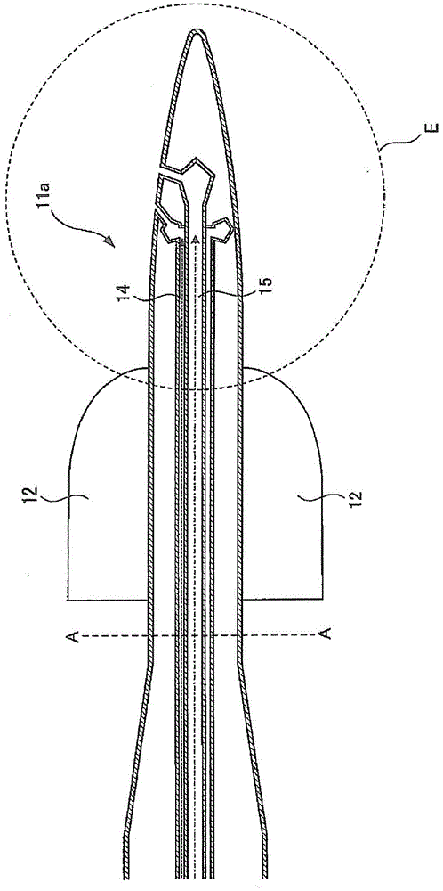
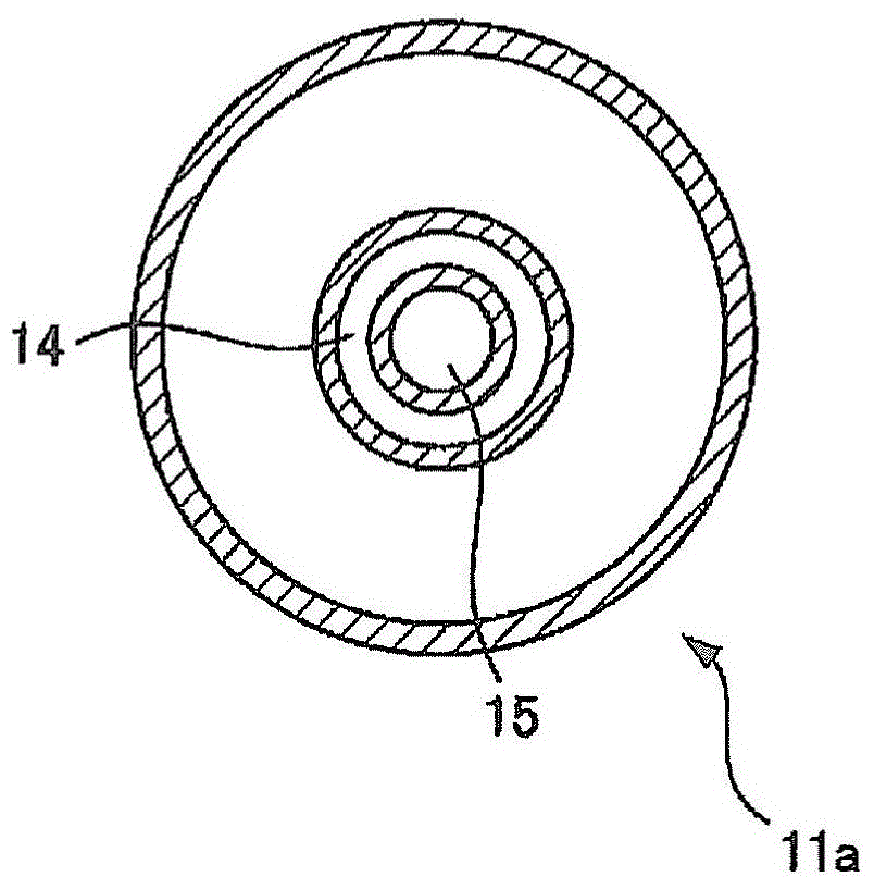
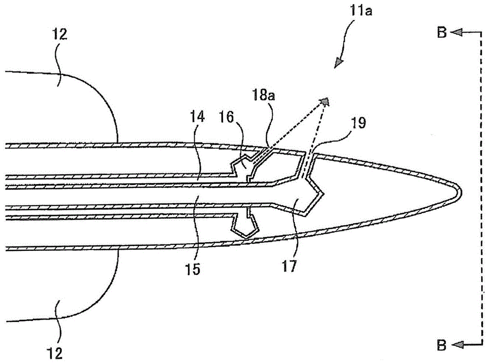
[0060] The fuel spray nozzle of Example 1 of the present invention will be described with reference to the drawings. figure 1 It is a schematic cross-sectional view for explaining the fuel spray nozzle of Example 1 of the present invention. figure 2 Yes figure 1A-A sectional view of . image 3 Yes figure 1 Enlarged view of part E in . Figure 4 Yes image 3 B-B arrow view. in addition, figure 1 , 3 The dashed arrow marks in , indicate the flow of additives, and the dashed arrow marks indicate the flow of liquid fuel.
[0061] The fuel spray nozzle 11a sprays liquid fuel and additives in the combustor of the gas turbine not shown, such as Figures 1 to 4 As shown, the rotary vane 12 , the additive flow path 14 , the liquid fuel flow path 15 , the additive pressure equalization space 16 , the liquid fuel pressure equalization space 17 , the first additive injection hole 18 a , and the liquid fuel injection hole 19 are provided.
[0062] The liquid fuel flow path 15...
Embodiment 2
[0079] The fuel spray nozzle of Example 2 of the present invention will be described with reference to the drawings. Figure 5 It is an enlarged schematic view of a part of the fuel spray nozzle of Example 2 of the present invention. Image 6 Yes Figure 5 C-C arrow view. in addition, Figure 5 The dashed-dotted arrow marks in the arrows show the flow of the liquid fuel, and the dotted portion shows the injected additive.
[0080] like Figure 5 , 6 As shown, the fuel spray nozzle 11b includes a rotary vane 12, a second additive injection hole 18b, a liquid fuel injection hole 19, an additive flow path (not shown), a liquid fuel flow path (not shown), and a space for additive pressure equalization (not shown). Not shown) and a space for liquid fuel pressure equalization (not shown). In addition, the rotary vane 12 , the liquid fuel injection hole 19 , the additive flow path, the liquid fuel flow path, the additive pressure equalization space, and the liquid fuel pressure...
Embodiment 3
[0088] The fuel spray nozzle of Example 3 of the present invention will be described with reference to the drawings. Figure 7 It is an enlarged schematic view of a part of the fuel spray nozzle of Example 3 of the present invention. Figure 8 Yes Figure 7 D-D arrow view. in addition, Figure 7 The dashed-dotted arrow marks in the arrows show the flow of the liquid fuel, and the dotted portion shows the injected additive.
[0089] like Figure 7 , 8 As shown, the fuel spray nozzle 11c includes a rotary vane 12, a third additive injection hole 18c, a liquid fuel injection hole 19, an additive flow path (not shown), a liquid fuel flow path (not shown), and a space for additive pressure equalization (not shown). Not shown) and a space for liquid fuel pressure equalization (not shown). In addition, the rotary vane 12, the liquid fuel injection hole 19, the additive flow path, the liquid fuel flow path, the additive pressure equalization space, and the liquid fuel pressure e...
PUM
 Abstract
Description
Claims
Application Information