Method for straw crushing and field-returning and mulching film recycling operation
A technology for mulching film and stalk, which is applied in the field of crop stalk crushing and returning to the field and mulching film recycling, can solve problems such as difficulty in mulching film recycling, and achieve the effects of high operation efficiency, improved recycling efficiency and concentrated operation.
- Summary
- Abstract
- Description
- Claims
- Application Information
AI Technical Summary
Problems solved by technology
Method used
Image
Examples
Embodiment 1
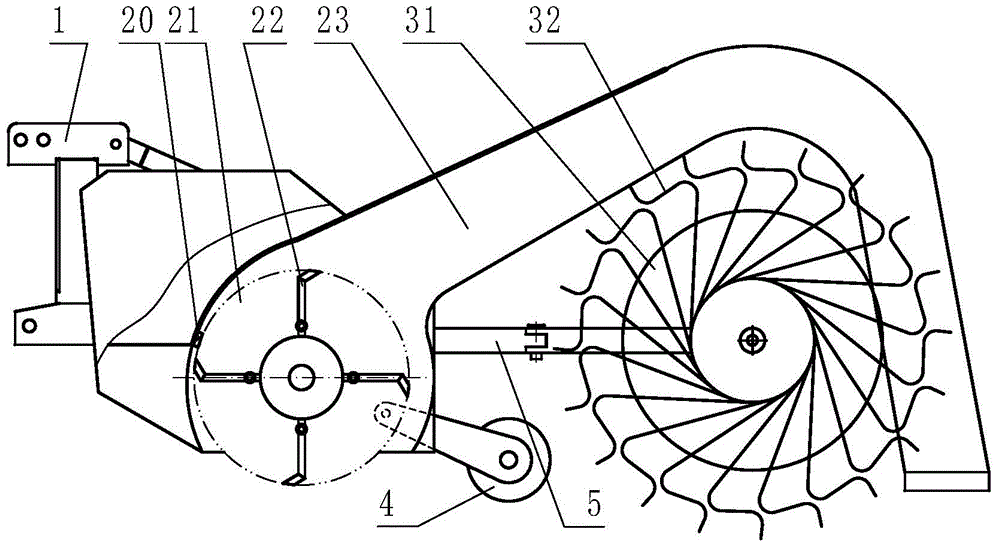
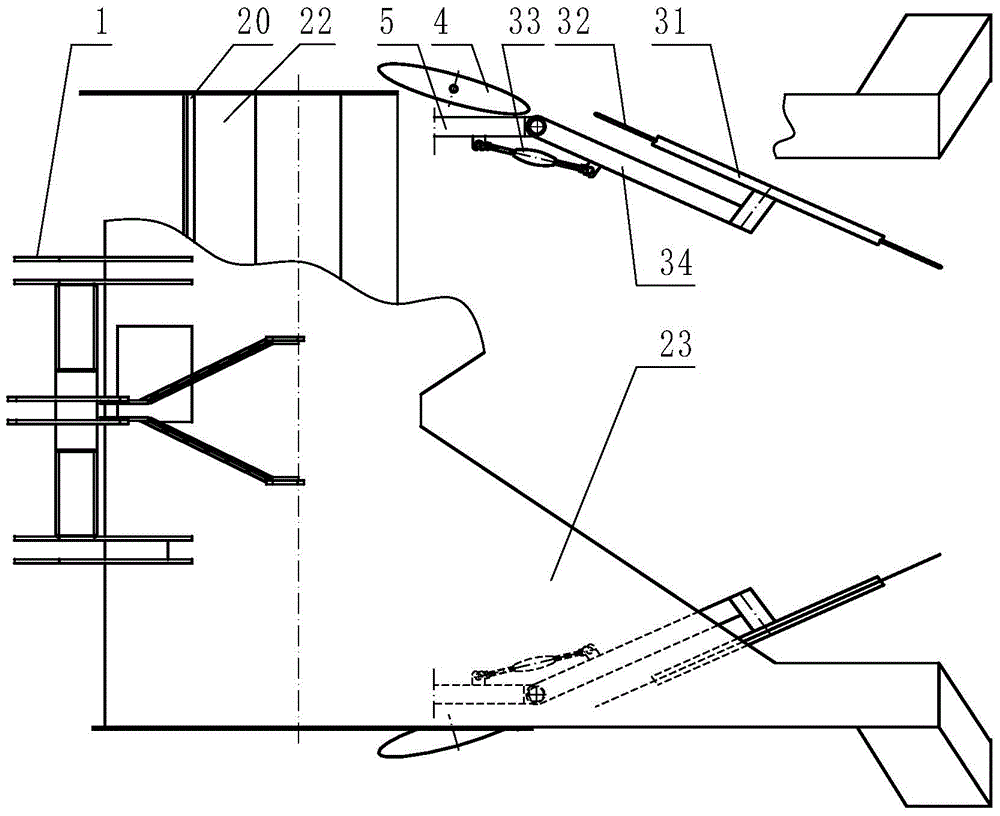
[0057] Embodiment 1: with reference to attached figure 1 , figure 2 , is a schematic structural view of the integrated operating machine for crushing and returning mulch film to the field according to Embodiment 1 of the present invention, including a traction or suspension frame 11, a frame 12 and a transmission mechanism, and the frame 12 is sequentially provided with a stalk crushing mechanism, The film edge lifting mechanism 4 and the horizontal membrane mechanism, the stalk crushing mechanism includes a crushing chamber 21, the crushing chamber 21 is a horizontal cylindrical body, the cylindrical body is provided with a fixed knife 20, and the crushing chamber 21 is provided with a rotary knife 22. The rotary knife 22 is set on a drum body. There are two openings on the wall of the cylindrical body of the crushing chamber 21. One opening is located at the front and lower part of the cylindrical body, which is the entrance of the stem, and the other opening is located at ...
Embodiment 2
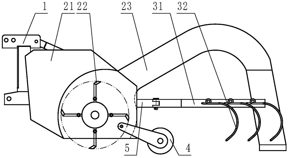
[0063] Embodiment 2: refer to image 3 , Figure 4 , which is a structural schematic diagram of Embodiment 2 of the present invention. Compared with Embodiment 1, the difference of this embodiment is that: the arm frame 31 of the horizontal membrane mechanism is a frame body, and the frame body is densely covered with tooth bars 32 Form the rake body, and the rake body is arranged on the frame 12 in a group of two in an inverted "eight" shape inclined or transversely.
Embodiment 3
[0064] Embodiment 3: refer to Figure 5-Figure 7 , is a structural schematic diagram of Embodiment 3 of the present invention. Compared with Embodiment 1, the difference of this embodiment is that: the arm frame 31 of the horizontal membrane mechanism is a chain, and tooth bars 32 are densely distributed on the chain to form The rake body, two groups of rake bodies are inclined or transversely arranged on the frame 12 in an inverted "eight" shape, and are driven by the sprocket 35.
PUM
 Abstract
Description
Claims
Application Information
 - R&D
- Intellectual Property
- Life Sciences
- Materials
- Tech Scout
- Unparalleled Data Quality
- Higher Quality Content
- 60% Fewer Hallucinations
Browse by: Latest US Patents, China's latest patents, Technical Efficacy Thesaurus, Application Domain, Technology Topic, Popular Technical Reports.
© 2025 PatSnap. All rights reserved.Legal|Privacy policy|Modern Slavery Act Transparency Statement|Sitemap|About US| Contact US: help@patsnap.com


