Particle matter moving bed dust removal device and dust removal method used by dust removal device

A technology of dust removal device and moving bed, which is used in combination devices, separation methods, dispersed particle filtration, etc., can solve the problems of thin components, complex structure, uneven heating, etc., to accelerate recycling, improve dust removal efficiency, and ensure normal operation. running effect

Active Publication Date: 2015-10-14
北京恒丰亚业科技发展有限公司
View PDF3 Cites 7 Cited by
  • Summary
  • Abstract
  • Description
  • Claims
  • Application Information

AI Technical Summary

Problems solved by technology

[0003] The particle moving bed filter and dust collector in the prior art usually adopts a splint or screen structure, which has a complex structure, thin components, easy to cause uneven heating, and the large area affects the high temperature and high pressure resistance of the filter and dust collector; Directly pass the dusty gas into the filter dust collector without pre-collection of dust particles, so that the particle size in the moving bed is uneven, and larger particles will generate gaps when absorbing large dust particles, which is not conducive to fine dust particles The absorption of dust, especially the absorption of fine dust particles less than 10 μm is not obvious; in the process of particle recycling after gas dust removal, only the particle cleaner is used to remove dust particles once, which will make the particle cleaner clear dust Incomplete, the particles falling into the particle bed will also carry dust, and the separation efficiency of particles and dust is low

Method used


Image

  • Particle matter moving bed dust removal device and dust removal method used by dust removal device

Examples


Embodiment Construction

[0025] In order to make the purpose, technical solutions and advantages of the embodiments of the present invention clearer, the technical solutions in the embodiments of the present invention will be clearly and completely described below in conjunction with the drawings in the embodiments of the present invention. Obviously, the described embodiments It is a part of embodiments of the present invention, but not all embodiments. Based on the embodiments of the present invention, all other embodiments obtained by persons of ordinary skill in the art without making creative efforts belong to the protection scope of the present invention.

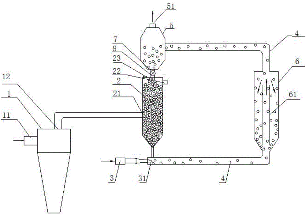
[0026] Such as figure 1 As shown, the particle moving bed dedusting device provided by the embodiment of the present invention includes a particle bed 2, a particle spray conveyor 3, a particle cleaner 5 and a spouted bed 6; the particle bed 2 is provided with a first air inlet 21 and a first The gas outlet 22 and the first air inlet 21 are ...


PUM


Abstract

The invention relates to the technical field of dust-containing air treatment devices and in particular relates to a particle matter moving bed dust removal device and a dust removal method used by the dust removal device. The particle matter moving bed dust removal device comprises a particle bed, a particle injection conveyor, a particle ash removal device and an injection bed, wherein a first air inlet and a first air outlet are formed in the particle bed; the lower end of the particle bed is connected with the lower end of the injection bed by a particle conveying pipe; the upper end of the injection bed is connected with the particle ash removal device by the particle conveying pipe; the particle ash removal device is connected with the upper end of the particle bed by a descending pipe; an air injection opening of the particle injection conveyor is connected with one end of the particle conveying pipe positioned at the lower end of the particle bed; the particle injection conveyor is inserted in one end of the particle conveying pipe by the air injection opening; a waste air outlet is formed in the particle ash removal device. According to the device and the method, dust-containing particles are pre-cleaned by adopting the injection bed, so that the separation efficiency of the dust-containing particles is improved, the cleanness of particles subjected to secondary air dust removal is ensured, and further the dust removal efficiency of the dust removal device is improved.

Description

technical field [0001] The invention relates to the technical field of dust-containing gas processing equipment, in particular to a particle moving bed dedusting device and a dedusting method thereof. Background technique [0002] At present, the granular bed used for gas filtration and dust removal can be divided into three basic modes: fixed bed, moving bed and fluidized bed according to the state of particle flow. The filtration efficiency of fluidized bed filter dust removal is low, and it can only be used for primary dust removal, and its application is seldom. The method of fixed bed filtration and dust removal has a high filtration efficiency when the particle layer is stationary; however, as an important part of the screen to support the particle layer and make the air flow evenly through the particle layer, the phenomenon of screen blockage and material leakage is prone to occur, and the screen The net cannot be made of high-temperature-resistant materials with poo...

Claims


Application Information

Patent Timeline
Patent Type & Authority Applications(China)
IPC IPC(8): B01D46/32B01D50/00
Inventor 陈水渺张宏伟梅磊吴道洪
Owner 北京恒丰亚业科技发展有限公司
Why Eureka
Try Eureka