Auxiliary tool for self-plugging rivet and use method thereof

A core blind rivet and auxiliary tool technology is applied in the field of rivets to achieve the effects of convenient installation and removal, stable riveting and convenient placement

Active Publication Date: 2015-10-14
CHONGQING JIANGLU LASER TECH
View PDF9 Cites 2 Cited by
  • Summary
  • Abstract
  • Description
  • Claims
  • Application Information

AI Technical Summary

Problems solved by technology

[0004] The invention provides an auxiliary tool for a blind rivet and a method of using the same to solve the problem that there is no auxiliary tool for guiding the expansion of the deformable section of the blind rivet body, causing the deformable sections of the blind rivet to expand in a lump question

Method used


Image

  • Auxiliary tool for self-plugging rivet and use method thereof
  • Auxiliary tool for self-plugging rivet and use method thereof
  • Auxiliary tool for self-plugging rivet and use method thereof

Examples


Embodiment 1

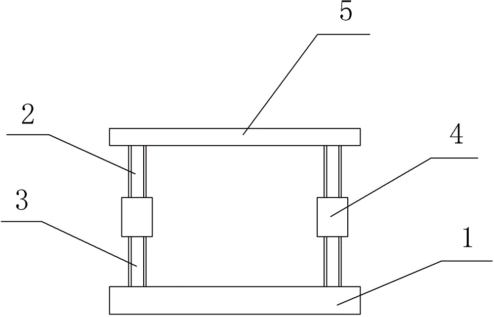
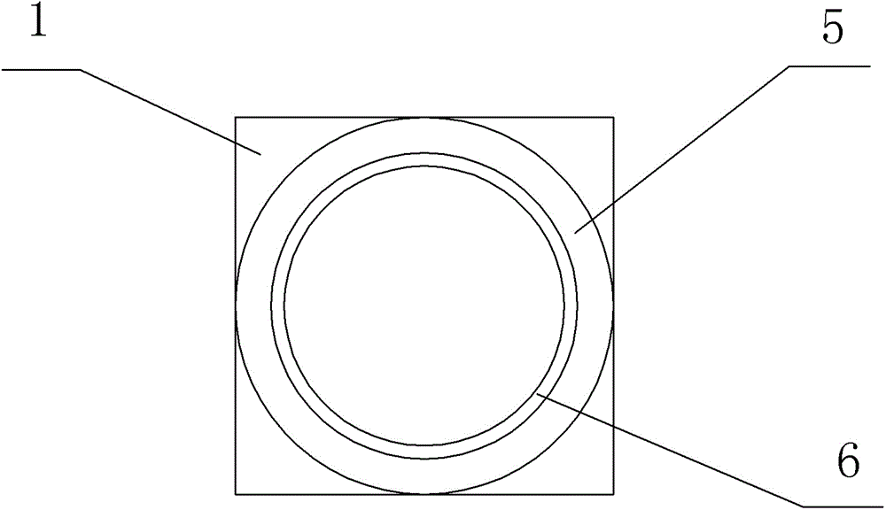
[0026] Such as figure 1 and figure 2 As shown, an auxiliary tool for blind rivets in this embodiment includes a base 1 , an adjusting rod and a fixing ring 5 . The quantity of adjusting rod is four, and adjusting rod is evenly distributed along the circumference of fixed ring 5, because adjusting rod is used for supporting fixed ring 5, adjusting rod 5 supports fixed ring up and down left and right, can make this structure more stable. The adjusting rod is mainly composed of a first screw 2, a second screw 3 and a sleeve 4, the sleeve 4 is threadedly connected to the lower end of the first screw 2 and the upper end of the second screw 3 respectively, and the upper end of the first screw 2 is connected to the base 1 Above, the lower end of the second screw rod 3 is connected to the back or outer edge of the fixing ring 5 . The inner edge of the fixed ring 5 is provided with a buffer pad 6, the inner diameter of the fixed ring 5 is less than the diameter of the deformable sec...

Embodiment 2

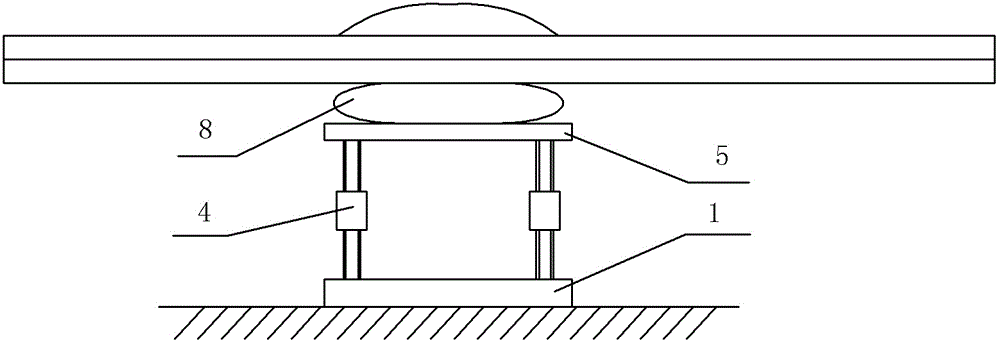
[0037] Such as Figure 4 As shown, the difference between the present embodiment and the first embodiment is that: the back of the base 1 is provided with a suction cup 7 . When there is a planar plate body on the other side of the riveting (that is, a narrow space), the suction cup 7 can be adsorbed on the plate body, which can make the structure more stable and less prone to deviation.


PUM

PropertyMeasurementUnit
diameteraaaaaaaaaa
thicknessaaaaaaaaaa
thicknessaaaaaaaaaa

Abstract

The invention discloses an auxiliary tool for a self-plugging rivet. The auxiliary tool comprises a base, a regulating rod and a fixed ring, wherein the regulating rod mainly consists of a first screw rod, a second screw rod and a sleeve, the sleeve is in threaded connection with one ends of the first screw rod and the second screw rod respectively, the other end of the first screw rod is connected to the base, and the other end of the second screw rod is connected to the back surface or the outer edge of the fixed ring; the inner diameter of the fixed ring is smaller than the diameter of a deformable section of the self-plugging rivet. According to the auxiliary tool disclosed by the invention, the fixed ring is used for being abutted to the deformable section of the self-plugging rivet when a nail core is drawn out, so that the downward expansion of the deformable section is limited; the nail core and the deformable section extend to two sides as much as possible, areas of expansion parts on the two sides are enlarged, and a rivet body is not liable to drop out of a mounting hole, so that the rivet connection is steadier; the regulating rod adopts a structure with a regulable length, the other end of the second screw rod is connected to the fixed ring, and the height of the fixed ring can be regulated through the length of the regulating rod, so that the fixed ring is convenient to mount and take out.

Description

technical field [0001] The invention belongs to the technical field of fasteners, in particular to rivets. Background technique [0002] Blind rivets are a type of rivets for single-sided riveting, including a riveting body and a mandrel. The riveting body is a hollow structure. One end of the riveting body is provided with a limit cap. in vivo. When riveting, the rivet mandrel is pulled by a special riveting gun to expand the deformable section of the riveting body to play the role of riveting. This type of rivet is especially suitable for riveting occasions where it is inconvenient to use ordinary rivets (riveting must be done from both sides), so it is widely used in construction, automobiles, ships, aircraft, machines, electrical appliances, furniture and other products. The biggest advantage of using blind rivets is to achieve single-sided riveting, because the other side is often in a small space, and it is inconvenient to rivet the other side. [0003] When using b...

Claims


Application Information

Patent Timeline
Patent Type & Authority Applications(China)
IPC IPC(8): B21J15/04B21J15/38
CPCB21J15/043B21J15/38
Inventor 吴德庆
Owner CHONGQING JIANGLU LASER TECH
Why Eureka
Try Eureka