Display device attachment fitting and display device attachment jig

A display device and installation tool technology, which is applied to identification devices, manufacturing tools, fixing devices, etc., can solve problems such as difficult wall-mounted installation devices and display device position accuracy, and achieve the effect of improving position accuracy

Active Publication Date: 2015-10-14
PANASONIC CORP
View PDF6 Cites 5 Cited by
  • Summary
  • Abstract
  • Description
  • Claims
  • Application Information

AI Technical Summary

Problems solved by technology

[0007] However, in the structure of the above-mentioned wall-mounted installation devices, only the installation accuracy of each wall-mounted installation device relative to the

Method used


Image

  • Display device attachment fitting and display device attachment jig
  • Display device attachment fitting and display device attachment jig
  • Display device attachment fitting and display device attachment jig

Examples


Example Embodiment

[0038] (Embodiment 1)

[0039] Regarding the mounting fitting (display device mounting fitting) 12 of one embodiment of the present disclosure to the display unit 10 of the display device 11, use Figure 1~Figure 14 It is explained as follows.

[0040] It should be noted that the up and down, left and right directions appearing in the following description refer to the up and down and left and right directions viewed from the front in a state where the display unit 10 is fixed to the wall surface 15.

[0041] [Structure of Display Unit 10]

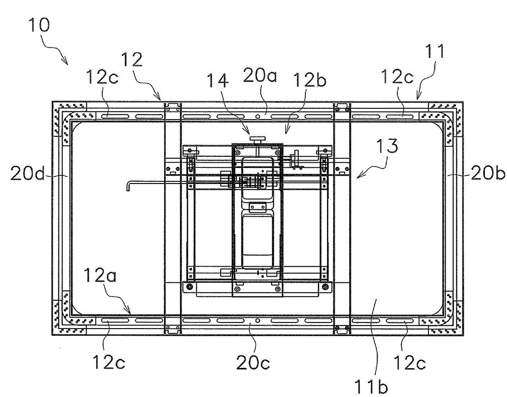
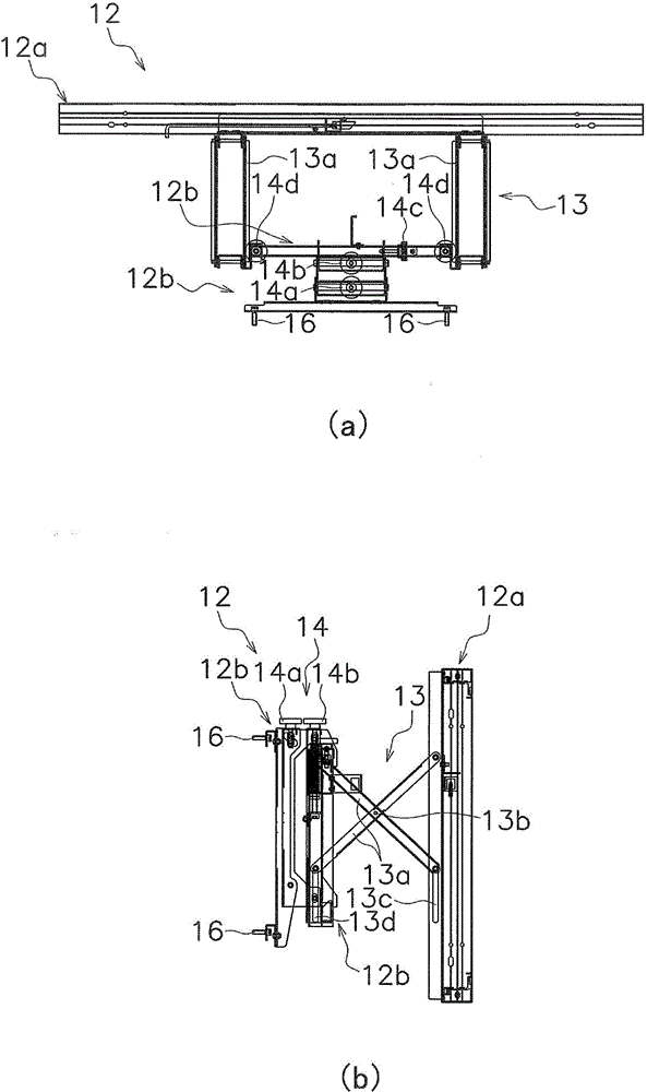
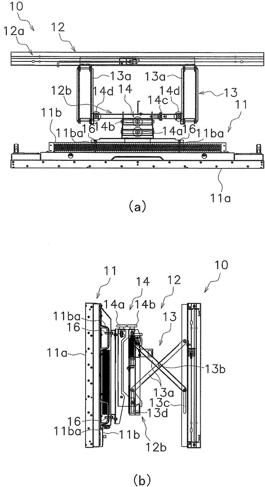
[0042] The display unit 10 of this embodiment is a unit for combining a plurality of display devices 11 in the vertical and horizontal directions to form a large screen, such as figure 1 As shown, a display device 11, a mounting accessory 12, a moving mechanism 13, and a fine adjustment mechanism 14 are provided.

[0043] (Display device 11)

[0044] The display device 11 is, for example, a display device such as a liquid crystal display and a plasma...

Example Embodiment

[0132] (Embodiment 2)

[0133] Regarding the corner fitting (display device mounting tool) 50 of other embodiments of the present disclosure, use Figure 15 ~ Figure 20 It is explained as follows.

[0134] That is, as with the corner fitting 30 of the first embodiment described above, a large screen is formed by combining a plurality of display devices 11 (refer to Image 6 ), in order to align the positions of the adjacent display devices 11 in the direction perpendicular to the display screen 11a, such as Figure 15 (a) and Figure 15 As shown in (b), the corner fittings 50 of this embodiment are attached to the four corners of the display device 11.

[0135] And like Figure 16 (a)~ Figure 16 As shown in (c), the corner fitting 50 has a main body 51, a magnet (adsorption part) 52, and a bolt 53.

[0136] Such as Figure 16 (a)~ Figure 16 As shown in (c), the main body part 51 is formed by combining flat-plate-shaped members, and has a connecting plate 51a, a flat part (first tool...

Example Embodiment

[0155] (Embodiment 3)

[0156] Regarding the corner fitting (display device installation tool) 150 of still another embodiment of the present disclosure, use Figure 21 , Figure 22 (a) and Figure 22 (b) The description is as follows.

[0157] It should be noted that the same reference numerals are given to the components common to the corner fitting 50 of the above-mentioned second embodiment, and detailed descriptions are omitted.

[0158] Here, in the operation of combining a plurality of display devices 11 to form a large screen, the image 3 (a) and image 3 (b) Under the operating state shown, adjust the position of each display device 11 and repeat the orientation Figure 4 (a) and Figure 4 (b) The operation of setting state transition as shown.

[0159] At this time, in the case of positioning the display devices 11 adjacent to each other, the outer peripheral surface of the magnet 52 is fitted into the recess 51ca disposed opposite to it, but the above-mentioned work state a...


PUM


Abstract

An attachment fitting 12 comprises a frame body 12a, a fitting component 12b, and fixing bolts 17. The frame body 12a is externally the same size as a display device 11, and is attached to a wall surface 15, and has stiffness property enough to support the weight of the display device 11. The fitting component 12b is provided to the frame body 12a on the side where the display device 11 is attached, and supports the rear face 11b side of the display device 11. The fixing bolts 17 are provided to the side faces of the frame bodies 12a, and fix the frame bodies 12a to each other in a state of being in contact with the side faces of the frame bodies 12a included in attachment fittings 12 of display devices 11 attached at adjacent positions.

Description

technical field [0001] In recent years, there has been an increasing demand for large display screens formed by combining display devices such as liquid crystal display panels and plasma display panels vertically and horizontally. Background technique [0002] As a mounting bracket used when combining multiple display devices vertically or horizontally to form a large display screen, a frame-shaped fixing frame fixed to a mounting surface such as a wall or a frame is used, and the front side of the fixing frame is fixed to the front side of the fixing frame. A component made of a frame-like movable frame that is pulled out. [0003] For example, Patent Document 1 (Japanese Unexamined Patent Application Publication No. 2011-75757) discloses a wall-mounted mounting device for mounting a predetermined display device on a wall, which includes: surface; the opening for hanging, which can hang the installation surface of the frame through the prescribed accessories provided on th...

Claims


Application Information

Patent Timeline
IPC IPC(8): B25B27/00G09F9/00
CPCA47B97/001F16B1/00F16B2001/0035F16M13/022H04N5/645H04N5/655B25B11/02B25B27/00F16B2200/83F16M11/041F16M11/045F16M11/046F16M11/10F16M11/18F16M11/2092F16M13/02G09F9/3026
Inventor 大宅智之饭村仁一
Owner PANASONIC CORP
Why Eureka
Try Eureka