
Improved electric car structure

A technology for electric vehicles and frames, which is applied in the field of improving the structure of electric vehicles. It can solve the problems of the weakening of the shock absorber itself, the reduction of the life of the range extender, and the damage of the range extender. Effect

Inactive Publication Date: 2015-10-14
SANMING UNIV
View PDF7 Cites 2 Cited by
  • Summary
  • Abstract
  • Description
  • Claims
  • Application Information

AI Technical Summary

Problems solved by technology

In addition, the range extender, which is also installed on the front side of the vehicle frame, is likely to reduce the service life of the range extender due to long-term shaking in the vehicle body. On the other hand, it may also cause pressure or impact on the circuit of the charging device and thus affect it.
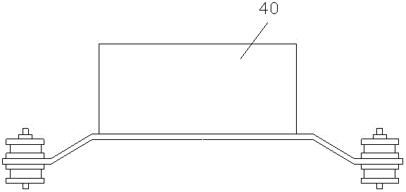
[0003] Therefore, it is necessary to install a shock absorber under the range extender, such as figure 1 Shown is the shock absorber structure of the range extender of the existing range-extended electric vehicle on the market. The structure is composed of rubber pads at both ends of the arc. The bolts are fixed, and the upper and lower ends are equipped with metal gaskets. The shock absorption effect of this structure can only meet the national standard. After a period of use, the effect of the shock absorber itself is weakened, which will lead to failure to meet the national standard and easily cause damage to the range extender.

Method used


Image

  • Improved electric car structure
  • Improved electric car structure
  • Improved electric car structure

Examples


Embodiment Construction

[0024] The present invention will be described in further detail below in conjunction with the accompanying drawings and specific embodiments.

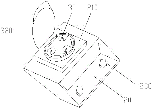
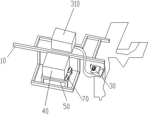
[0025] Such as Figure 1~2 As shown, an improved structure of an electric vehicle, a hybrid electric vehicle charger, includes a vehicle frame 10 at the front of the vehicle body, and a lateral support plate 20 is fixed to the side of the vehicle frame 10 at the front of the vehicle body, and the support plate A charging socket 30 is embedded in the middle of the vehicle body, and an energy storage device 310 is arranged on the frame 10 at the front side of the vehicle body, and the energy storage device 310 is connected to the charging socket 30 via a line.

[0026] The support plate 20 is stepped, and the outer step surface of the support plate is connected with the frame at the front side of the car body through bolts 230. The support plate 210 is threaded on the support plate, and the charging socket 30 is embedded in the support....


PUM

PropertyMeasurementUnit
Bending angleaaaaaaaaaa

Abstract

The invention provides an improved electric car structure. The improved electric car structure comprises a car frame on the front portion of a car body. A transverse supporting board is fixed to the lateral portion of the car frame of the front portion of the car body. A charging socket is embedded in the middle of the supporting board. An energy storage device is arranged on the car frame on the front lateral portion of the car body and electrically connected with electric equipment and the charging socket through lines. In addition, a car frame range extender damping device is improved; the charging socket of the improved structure is arranged in a forecabin; the layout of a charging circuit is optimized; the circuit is shortened; hidden dangers of high temperature ignition are eliminated; the cost is reduced; installation locations are reasonable due to the wide space; the charging socket is fixed more firmly due to the fixing mode. Meanwhile, the damping device is in a damper shape with the rhombohedron section, in this way, the shear stress principle is well utilized, vibration in a single direction can be dispersed to be in different directions, and the damping effect is greatly improved. By the adoption of the structure, the improved electric car structure is simple in process and low in cost compared with a traditional structure.

Description

technical field [0001] The invention relates to an improved structure of an electric vehicle. Background technique [0002] At present, the charging port and fuel filling port of hybrid electric vehicles (or extended-range electric vehicles) on the market are arranged together and placed at the rear of the vehicle, which has potential safety hazards. Ignite gasoline and cause damage, etc. In view of such disadvantages, the arrangement of the charging port of this extended-range electric vehicle fully takes this problem into consideration. The charging port and the fuel port are arranged separately. It also makes the arrangement easier and more convenient. In addition, the range extender, which is also installed on the front side of the vehicle frame, is likely to reduce the service life of the range extender due to long-term shaking in the vehicle body. On the other hand, it may also cause pressure or impact on the circuit of the charging device, thereby affecting it. [...

Claims


Application Information

Patent Timeline
IPC IPC(8): B60L11/18
CPCY02T10/70
Inventor 郑飞杰冯彬
Owner SANMING UNIV
Learn More