
Vertical sand silo and application method thereof

A technology of vertical sand silo and silo body, which is applied in the directions of earthwork drilling, filling, safety device, etc., can solve the problems of high processing cost, waste of resources, long time consumption, etc., to increase the settlement space and increase the settlement effect. , the effect of tailings concentration reduction

Inactive Publication Date: 2015-10-14
FENY
View PDF7 Cites 2 Cited by
  • Summary
  • Abstract
  • Description
  • Claims
  • Application Information

AI Technical Summary

Problems solved by technology

When the vertical sand bin is used for tailings settlement and separation treatment, since the solid-liquid separation of tailings settlement mainly adopts gravity sedimentation, it often takes a long time, and the concentration of tailings in the overflow water separated from the tailings is too high , the waste of tailings is large, and the follow-up treatment cost of overflow water is high. In order to reduce the settling time, operators often add a small amount of flocculant to the tailings slurry to speed up the settlement of tailings and the clarification of overflow water. However, adding flocculants Although the concentration of tailings in the overflow water can be reduced, the separated overflow water cannot be reused by the mine, which increases the production cost of the mine; in addition, in order to ensure the continuity of production, the mine generally needs to prepare a The vertical sand bin is used for backup, and this spare vertical sand bin is often used less often, which seriously causes a waste of resources

Method used


Image

  • Vertical sand silo and application method thereof
  • Vertical sand silo and application method thereof

Examples


Embodiment Construction

[0027] In order to enable those skilled in the art to better understand the technical solutions in the present application, the technical solutions in the embodiments of the present application will be clearly and completely described below in conjunction with the drawings in the embodiments of the present application. Obviously, the described The embodiments are only some of the embodiments of the present application, but not all of them.

[0028] Based on the embodiments in this application, all other embodiments obtained by persons of ordinary skill in the art without creative efforts shall fall within the scope of protection of this application.

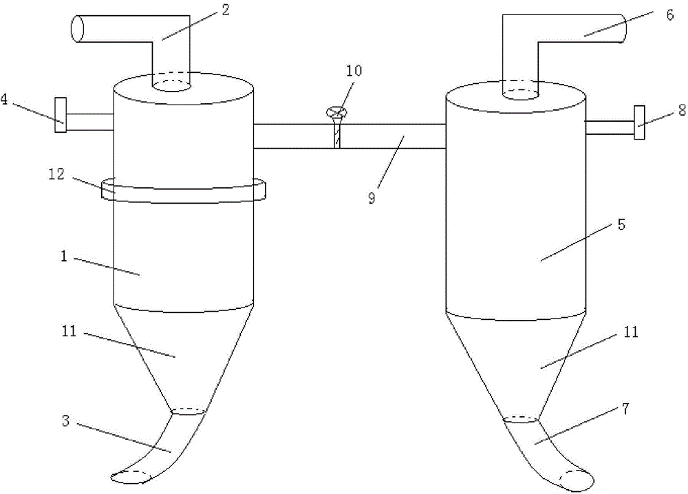
[0029] See attached figure 2 , with figure 2 A specific embodiment of a vertical sand bin is provided, wherein, the attached figure 2 It is a schematic diagram of the overall structure of the vertical sand bin.

[0030] as attached figure 2 As shown, the vertical sand bin includes a first bin body 1 and a second bin body ...


PUM


Abstract

The invention discloses a vertical sand silo. The vertical sand silo comprises a first silo body and a second silo body. The top of the first silo body is provided with a first feeding pipe used for conveying slurries of milltailings to be settled into the interior of the first silo body. The bottom of the first silo body is provided with a first discharge pipe used for conveying milltailings to be settled out to the exterior of the first silo body. A first water overflow valve is arranged at the upper portion of the first silo body and used for controlling output of overflow water separated from the interior of the first silo body. At the same time, the top of the second silo body is provided with a second feeding pipe and the bottom of the second silo body is provided with a second discharge pipe. A second water overflow valve is arranged at the upper portion of the second silo body. A water guide pipe is arranged between the upper portion of the first silo body and the upper portion of the second silo body and used for communicating overflow water between the first silo body and the second silo body. The invention further discloses an application method of the vertical sand silo. By means of an above device and the method, sedimentation rate of milltailings can be increased without adding flocculants, concentration of milltailings of overflow water is reduced and waste if spare equipment is effectively avoided.

Description

technical field [0001] The invention relates to the field of tailings settlement treatment, and more specifically relates to a vertical sand bin and a method for using the same. Background technique [0002] In the process of mining, a large number of goafs are often produced, and if these goafs are not filled in time, it is easy to cause ground subsidence, seriously affecting the safety of people's production and life. In order to overcome the above defects, people often need to fill the goaf in time, and the high-concentration cemented filling technology with full tailings is a method commonly used by people at present. When using the full tailings high-concentration cemented filling technology, since the tailings directly mined from the mine often have a relatively high water content and are mixed with some other impurities, in order to ensure that the tailings can be closely combined with other filling materials, It is often necessary to treat the tailings first to make...

Claims


Application Information

Patent Timeline
IPC IPC(8): E21F15/10
Inventor 张泽武李书生刘侃文齐学民陈国强姜寄廖伟
Owner FENY
Learn More