in situ direct shear

A direct shear, in-situ technology, used in instruments, scientific instruments, and the use of stable shear force to test the strength of materials, etc., can solve the problem of measurement accuracy and accuracy changing soil properties, internal friction angle and cohesion. problems, to achieve the effect of improving uneven stress distribution, high work efficiency and moderate volume

Active Publication Date: 2017-07-21
北京隆盛元科技有限公司
View PDF6 Cites 0 Cited by
  • Summary
  • Abstract
  • Description
  • Claims
  • Application Information

AI Technical Summary

Problems solved by technology

When the existing direct shear instrument is used, it usually takes the sampling device and the soil back to the laboratory for measurement after sampling the soil. Due to the need to carry and move, it is inevitable that there will be various problems that affect the measurement accuracy and accuracy. Disturbance changes the properties of the soil, which causes the shear strength parameters of the soil measured by the direct shear instrument to be inconsistent with the actual situation, and the authenticity of the values ​​​​of the internal friction angle and cohesion obtained from this is poor

Method used


Image

  • in situ direct shear
  • in situ direct shear
  • in situ direct shear

Examples


Embodiment Construction

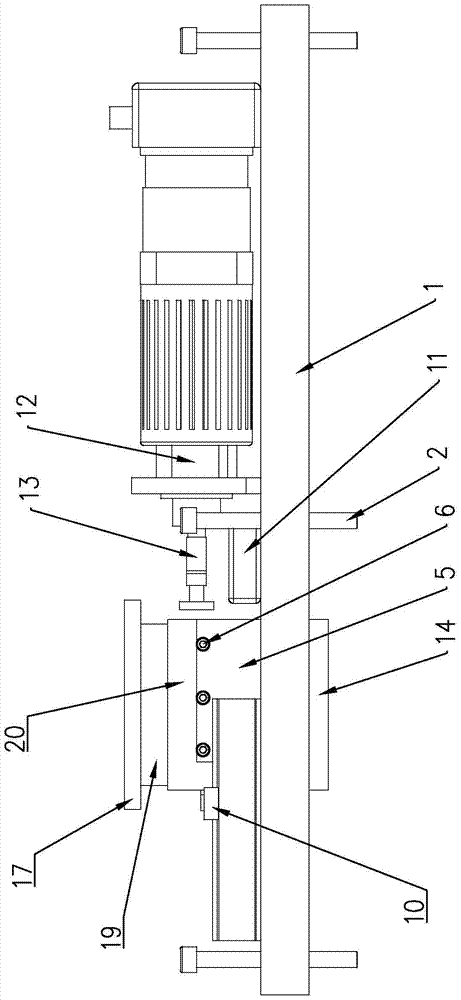
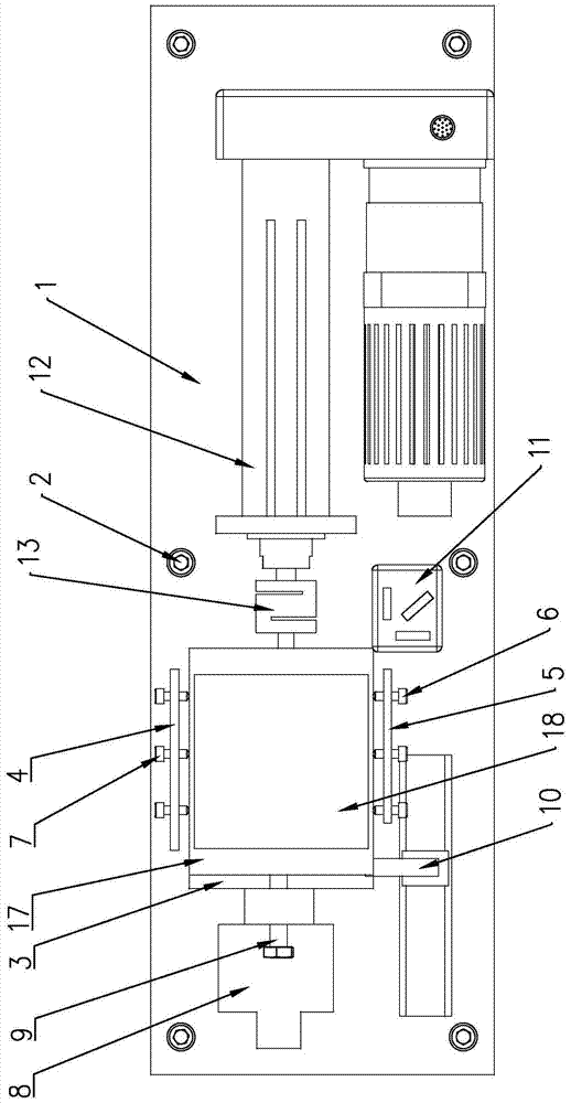
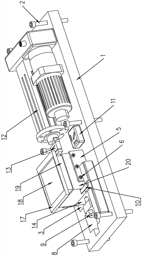
[0022] Such as figure 1 , figure 2 and image 3 As shown, the in-situ direct shear instrument of the present invention comprises a base plate 1, the plate surface of the base plate 1 is located in the horizontal direction, and the edge of the plate surface of the base plate 1 is screwed with a plurality of adjusting bolts for adjusting the levelness of the base plate 1 along the vertical direction 2. A level 11 for monitoring the flatness of the base plate 1 is provided on the upper end surface of the base plate 1. A rectangular soil shear box placement hole 3 is provided on the left half of the base plate 1. The soil shear box placement hole 3 is placed along the vertical The vertical direction runs through the board surface of the base plate 1, and the upper end surface of the base plate 1 is provided with a front fender 5 and a rear fender 4. The plate 5 is positioned at the front edge of the soil shear box placement hole 3, the rear baffle 4 is positioned at the rear si...


PUM


Abstract

The in-situ direct shear instrument includes a bottom plate. The edge of the bottom plate surface is screwed with a plurality of adjusting bolts for adjusting the levelness of the bottom plate along the vertical direction. A level for monitoring the flatness of the bottom plate is provided on the upper end of the bottom plate. The left half of the board surface is provided with a rectangular soil shear box placement hole, and the upper end surface of the bottom plate is provided with a front baffle and a rear baffle, the front baffle is located at the front edge of the soil shear box placement hole, and the rear baffle is The plate is located at the rear side edge of the hole where the soil shearing box is placed. The bottom ends of the front baffle and the rear baffle are respectively fixedly connected with the upper surface of the bottom plate. The limit adjustment screw, the rear limit adjustment screw of a plurality of soil shear boxes is screwed on the plate surface of the rear baffle. Its purpose is to provide an in-situ direct shear instrument that measures the shear strength parameters of the soil more in line with the actual situation, and the values ​​of the internal friction angle and cohesion obtained therefrom are more authentic and work more efficiently.

Description

technical field [0001] The invention relates to an in-situ direct shearing instrument. Background technique [0002] The direct shear instrument is mainly used to measure the shear strength parameters of soil, and obtain the values ​​of internal friction angle and cohesion through the relationship between shear force and displacement. When the existing direct shear instrument is used, it usually takes the sampling device and the soil back to the laboratory for measurement after sampling the soil. Due to the need to carry and move, it is inevitable that there will be various problems that affect the measurement accuracy and accuracy. Disturbance changes the properties of the soil, which causes the shear strength parameters of the soil measured by the direct shear instrument to be inconsistent with the actual situation, and the authenticity of the values ​​​​of the internal friction angle and cohesion obtained from this is poor. Contents of the invention [0003] The object...

Claims


Application Information

Patent Timeline
Patent Type & Authority Patents(China)
IPC IPC(8): G01N3/24G01N3/02
Inventor 李长隆李军金嗣淳李滨
Owner 北京隆盛元科技有限公司
Why Eureka
Try Eureka