Distributed Compact Sensing Matrix Tracking Method Based on Cross Array Radar System

A radar system and sensing matrix technology, applied in the field of distributed compact sensing matrix tracking, can solve the problems of increasing radar design cost and complex hardware system design

Inactive Publication Date: 2018-11-27
XI AN JIAOTONG UNIV
View PDF2 Cites 0 Cited by
  • Summary
  • Abstract
  • Description
  • Claims
  • Application Information

AI Technical Summary

Problems solved by technology

However, these works require the design of additional hardware systems to generate specific waveforms or realize sensing matrices, and the design of these hardware systems is very complicated, which increases the design cost of the radar to a certain extent

Method used


Image

  • Distributed Compact Sensing Matrix Tracking Method Based on Cross Array Radar System
  • Distributed Compact Sensing Matrix Tracking Method Based on Cross Array Radar System
  • Distributed Compact Sensing Matrix Tracking Method Based on Cross Array Radar System

Examples


Embodiment Construction

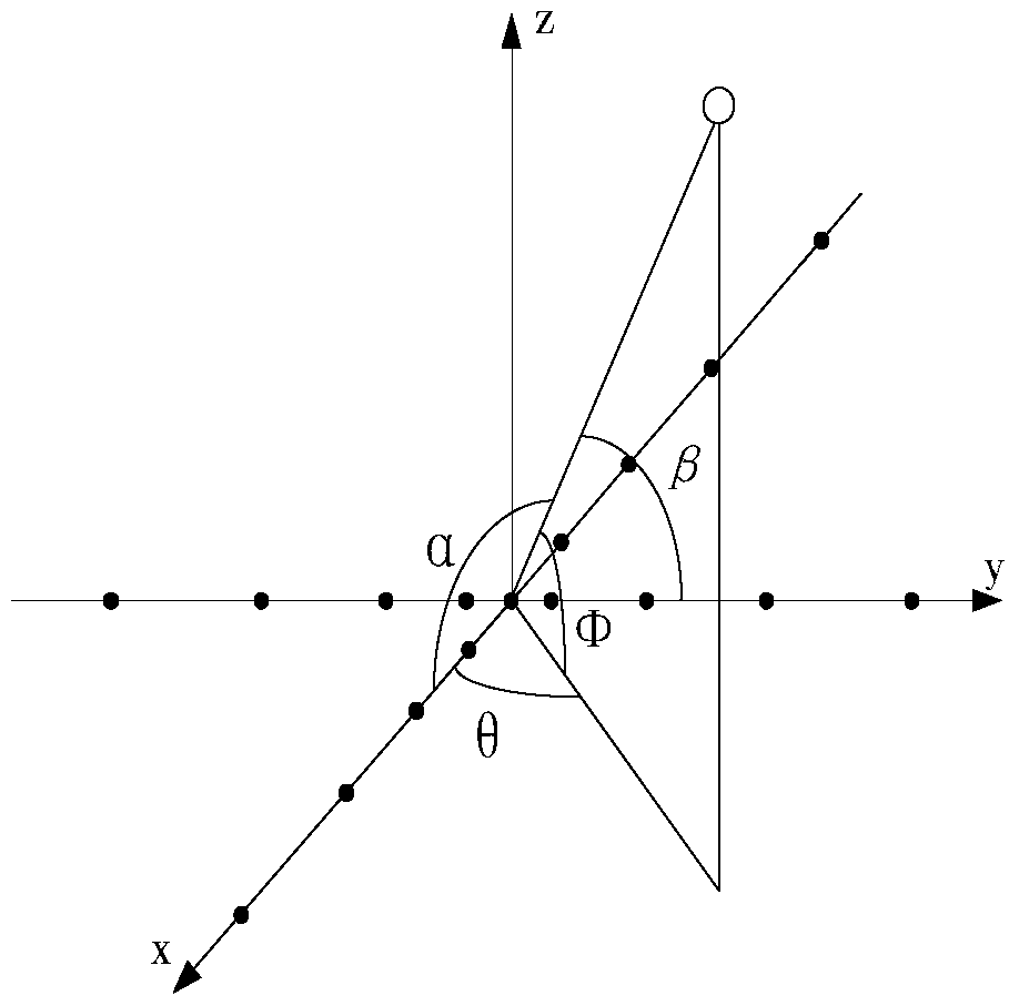
[0053] See Figure 1 to Figure 4 As shown, the present invention considers a cross array radar system installed on an airborne platform. The radar consists of two mutually perpendicular non-uniform linear arrays containing N array elements. The distance between the element of the non-uniform linear array and the origin satisfies the formula: d i =e (2.15+0.25i) , The unit is mm. Where d i Indicates the distance between the i-th element on the positive or negative semi-axis from the origin. The height of the airborne platform is H and it is fixed. The selected coordinate system is like figure 1 Shown. The angle variables φ and θ represent the pitch angle and the azimuth angle. The radar array element emits a chirp signal whose carrier frequency is f c =c / λ c , Where c is the propagation velocity, λ c Is the wavelength.

[0054] The following describes a typical array receiving signal model. First, consider that N far-field narrowband signals are incident on a certain array ...


PUM


Abstract

The invention discloses a distributed compact sensing matrix tracking method based on a cross array radar system, comprising the following steps: (1) obtaining compact sensing matrixes psiX and psiY according to sensing matrixes phiX and phiY corresponding to two arrays in a cross array radar; (2) carrying out processing by an orthogonal matching tracking algorithm to obtain initial estimates S(^)<ini><X> and S(^)<ini><Y> of a correct subspace; (3) forming two candidate column sets f(^)<X> and f(^)<Y> according to all the columns in a plurality of similar column groups corresponding to the initial estimates S(^)<ini><X> and S(^)<ini><Y>, performing union operation on the two candidate column sets to obtain the latest candidate column set f(^), performing permutation and combination on the columns to find a column combination minimizing the residual sum and obtain a correct support set; and (4) obtaining corresponding azimuth angle and pitching angle according to the correct support set. By constructing low-coherence compact sensing matrixes, the problem that a sparse vector cannot be perfectly reconstructed with large probability due to the fact that the original perception matrix has high coherence as the radar resolution increases is overcome, and the result is more accurate through fusion of the information of two columns.

Description

【Technical Field】 [0001] The invention relates to the technical field of radar signal processing, in particular to a distributed compact sensing matrix tracking method based on a high-resolution cross array radar system. 【Background technique】 [0002] Compressed sensing technology is widely used in radar signal processing systems. Compared with traditional radars, compressed sensing radar has the following advantages: 1) The radar signal processing system based on compressed sensing technology directly reconstructs the radar sparse scene according to the received echo signals, eliminating the need for matched filters at the receiving end [1] , So as to maintain the maximum original measurement information to the greatest extent; 2) The dimension of the data sampled by compressed sensing technology is far lower than the dimension of the data sampled following the Nyquist sampling theorem, but only proportional to the data sparsity , Thus realizing the acquisition of information i...

Claims


Application Information

Patent Timeline
Patent Type & Authority Patents(China)
IPC IPC(8): G01S7/41
CPCG01S7/41
Inventor 刘静盛明星宋大伟尚社韩崇昭
Owner XI AN JIAOTONG UNIV
Why Eureka
Try Eureka