Intelligent wireless cabinet fire monitoring system

A monitoring system and wireless machine technology, applied in the field of power system equipment monitoring, can solve the problems of no wireless fire monitoring system, poor timeliness, and high system cost, and achieve the effect of eliminating fire hazards

Active Publication Date: 2015-10-14
RES INST OF ECONOMICS & TECH STATE GRID SHANDONG ELECTRIC POWER +1
View PDF8 Cites 14 Cited by
  • Summary
  • Abstract
  • Description
  • Claims
  • Application Information

AI Technical Summary

Problems solved by technology

There is no internal fire monitoring and fire extinguishing system for the internal characteristics of the cabinet
[0005] Second, poor timeliness
The traditional method cannot detect the fire in the cabinet at the first time, and cannot extinguish the fire at the first time. It can only detect the fire when the smoke comes out of the cabinet or the heat dissipates to the outside of the cabinet after a fire for a period of time, and start the fire. Fire extinguishing function lag
[0006] Three is a big loss
In the traditional fire control system, only when the fire in the cabinet is large enough, the components in the cabinet have been burned and damaged seriously, or even the entire control room or the entire network frame is damaged, can the fire alarm system installed in the control room (outside the cabinet) alarm and fire. Fire extinguishing, resulting in serious equipment damage, long recovery period and high maintenance cost
[0007] Fourth, the system cost is high
The traditional security monitoring system uses wired communication instead of wireless communication technology, so a large number of flame-retardant signal cables are required, the construction is difficult and the investment cost is high
[0008] Fifth, the intelligent program is low
But at present, according to the documents published by the state, after searching relevant professional magazines, newspapers, and the Internet, there is no mature intelligent wireless fire monitoring system in China.

Method used


Image

  • Intelligent wireless cabinet fire monitoring system
  • Intelligent wireless cabinet fire monitoring system
  • Intelligent wireless cabinet fire monitoring system

Examples


Embodiment Construction

[0050] In order to clearly illustrate the technical features of this solution, the present invention will be described in detail below through specific implementation modes and in conjunction with the accompanying drawings. The following disclosure provides many different embodiments or examples for implementing different structures of the present invention. To simplify the disclosure of the present invention, components and arrangements of specific examples are described below. Furthermore, the present invention may repeat reference numerals and / or letters in different instances. This repetition is for the purpose of simplicity and clarity and does not in itself indicate a relationship between the various embodiments and / or arrangements discussed. It should be noted that components illustrated in the figures are not necessarily drawn to scale. Descriptions of well-known components and processing techniques and processes are omitted herein to avoid unnecessarily limiting the...


PUM


Abstract

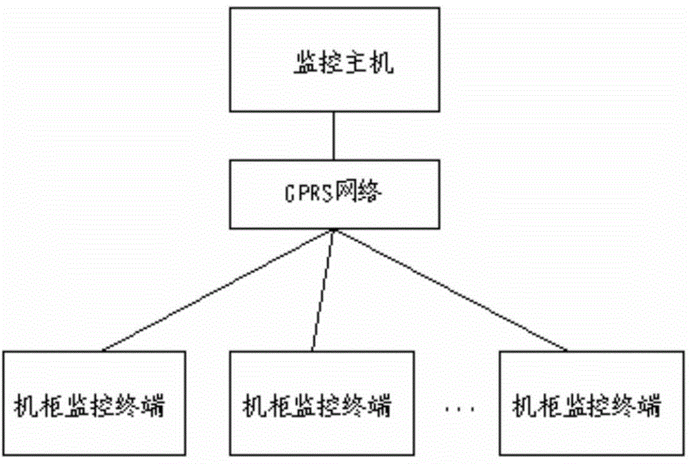
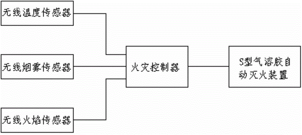
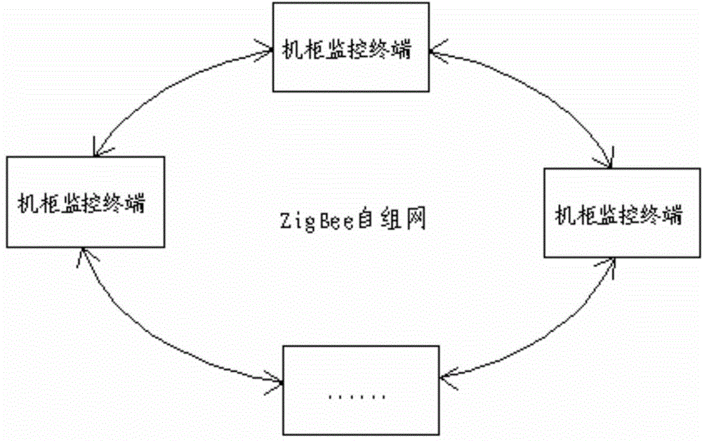
An intelligent wireless cabinet fire monitoring system comprises cabinet monitoring terminals of a fire detector, a fire controller, an automatic fire extinguishing device, etc. in the cabinet. The fire detector transmits detected temperature information, smoke information and fire information in the cabinet to the fire controller. The fire controller determines whether a fire disaster occurs according to the received data, and furthermore transmits a fire extinguishing instruction to the automatic fire extinguishing device for performing fire extinguishing operation. Simultaneously the fire controller stores the received data information and transmits the received data information to a monitoring host computer in a monitoring room in which the cabinet is arranged. The monitoring host computer is used for performing parameter setting, data displaying, early-warning analyzing, fire extinguishing controlling, history inquiring and decision supporting. The intelligent wireless cabinet fire monitoring system has the functions of monitoring an operation state in the cabinet in real time, intelligently determining the fire state in the cabinet, automatically performing a fire extinguishing treatment on the environment in the cabinet, and recording and storing the monitored data information from operation of the system, thereby performing intelligent prejudgement and analysis on the operation trend of the cabinet.

Description

technical field [0001] The invention relates to a monitoring system, in particular to an intelligent wireless cabinet fire monitoring system, which belongs to the technical field of power system equipment monitoring. Background technique [0002] The traditional cabinet fire control system is mainly composed of temperature sensor, smoke sensor, fire controller and intermodal host. The system is installed in the control room where the cabinet is located. When a fire occurs inside the cabinet (after the fire), the temperature sensor and The smoke sensor detects the temperature data and smoke signal in the control room (not inside the cabinet). When the temperature exceeds the set upper limit or the smoke data measured by the smoke sensor reaches the threshold, the fire controller or the linkage host will start the fire alarm function and start the manual fire alarm function. Or the automatic fire extinguishing function to control and extinguish the fire caused by the inside of...

Claims


Application Information

Patent Timeline
Patent Type & Authority Applications(China)
IPC IPC(8): G08B17/06G08B17/10
CPCG08B17/06G08B17/10
Inventor 李越卢福木刘海涛王庥祺丁晶梁腾龙张东峰张亮刘勇于昉李凯
Owner RES INST OF ECONOMICS & TECH STATE GRID SHANDONG ELECTRIC POWER
Why Eureka
Try Eureka