Lightning conductor with solar energy and windmill power generation

A solar power generation panel and windmill power generation technology, applied in the field of lightning rods, can solve the problems that lightning rods do not meet the needs of use, cannot use solar energy with maximum efficiency, and neglect renewable resources.

Active Publication Date: 2015-10-14
长沙市雷立行电子科技有限公司
View PDF6 Cites 6 Cited by
  • Summary
  • Abstract
  • Description
  • Claims
  • Application Information

AI Technical Summary

Problems solved by technology

[0002] The existing lightning rods are usually installed on the top of the building, just to prevent lightning strikes, without any other function, and the cost of installing lightning rods on the building is relatively high, and the probability of the building being struck by lightning during use is relatively low, and some Even after the lightning rod has reached its service life, it will be scrapped if it has not been struck by lightning, which is quite wasteful. This kind of lightning rod used simply for lightning protection has become increasingly unsatisfactory.
However, there are many natural resources on the top of the building that have not been developed. For example, the top of the building can receive long-te

Method used


Image

  • Lightning conductor with solar energy and windmill power generation
  • Lightning conductor with solar energy and windmill power generation
  • Lightning conductor with solar energy and windmill power generation

Examples


Embodiment

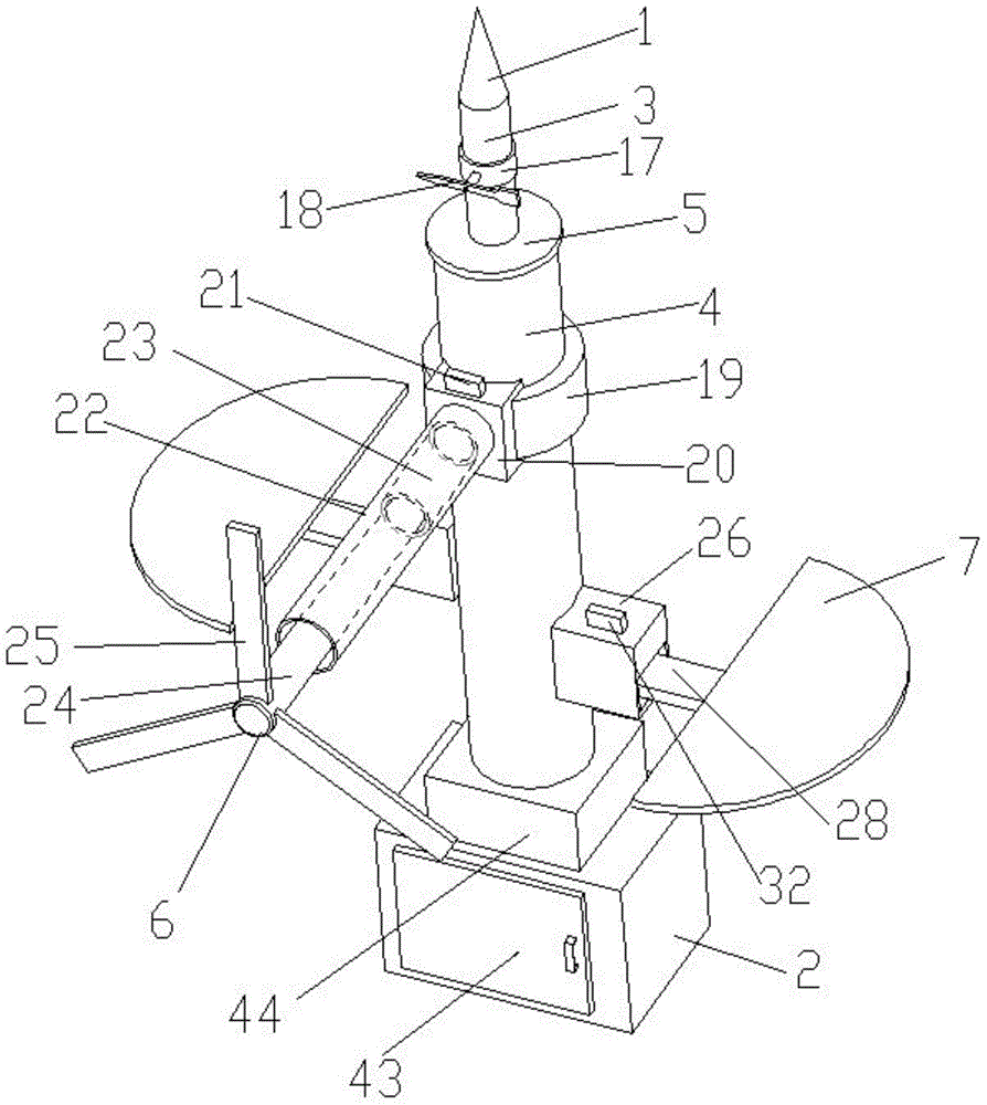
[0026] Embodiment: a lightning rod with solar energy and windmill power generation, comprising a lightning receptor 1, a base 2, and a conductive rod 3, the lower end of the conductive rod is fixed on the base, and the lightning receptor is fixed on the The upper end of the conductive rod also includes a hollow support column 4, the lower end of the support column is fixed on the base, the support column is sleeved on the conductive rod, the conductive rod is grounded, and the conductive rod The upper end of the upper end protrudes upwards from the support column, and the upper end of the support column is sealed and welded together with the conductive rod through an insulating plate 5, and the space between the support column and the conductive rod is vacuum-like;

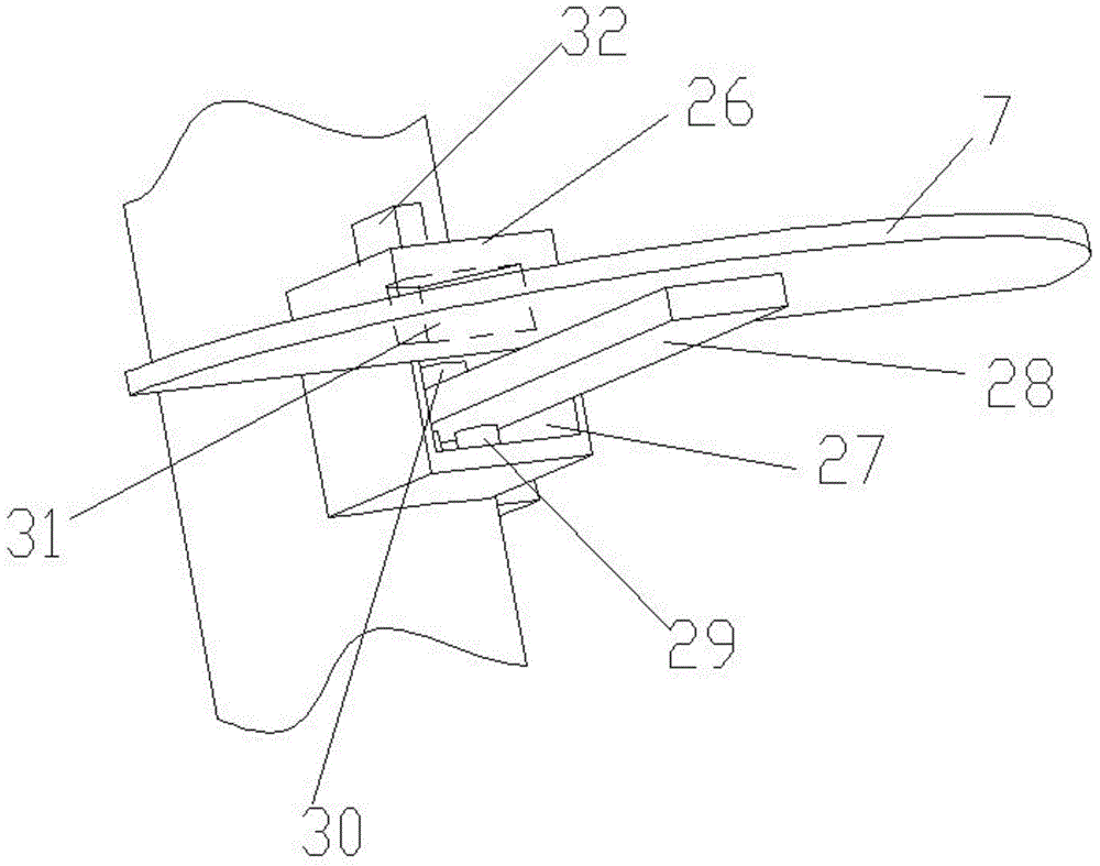
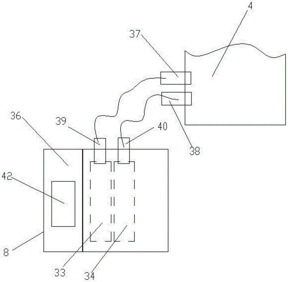
[0027] A windmill 6 and some solar power generation panels 7 through wind power generation are installed on the support column, an energy storage box 8 is placed in the base, and the windmill and solar power genera...


PUM


Abstract

The invention discloses a lightning conductor with solar energy and windmill power generation. The lightning conductor comprises a lightning arrester, a pedestal and a conductive rod and further comprises a hollow supporting column, wherein the supporting column is arranged on the conductive rod in a sleeving manner; the conductive rod is grounded; the upper end of the conductive rod upwards extends out of the supporting column; a windmill for wind power generation and a plurality of solar power generation panels are mounted on the supporting column, an energy storage box is placed in the pedestal, and the windmill and the solar power generation panels are electrically connected with the energy storage box; a ring of slide rail is fixedly arranged on the outer wall of the supporting column in a sleeving manner, a sliding block is slidably positioned on the slide rail, a wireless controller is fixedly arranged on the sliding block, the wireless controller can control the sliding block to slide and position on the slide rail, and the windmill is fixedly arranged on the sliding block; the solar power generation panels are fan-shaped, two positioning boxes are fixedly arranged on the supporting column, a notch is formed in each of the positioning boxes, a supporting plate is fixedly arranged on the bottom face of each of the solar power generation panels, and the supporting plate is arranged through the notch and swings up and down and is positioned in each of the positioning boxes. The lightning conductor disclosed by the invention can be used for utilizing wind energy and solar energy with maximum efficiency.

Description

technical field [0001] The invention relates to a lightning rod, in particular to a lightning rod with solar energy and windmill power generation. Background technique [0002] The existing lightning rods are usually installed on the top of the building, just to prevent lightning strikes, without any other function, and the cost of installing lightning rods on the building is relatively high, and the probability of the building being struck by lightning during use is relatively low, and some Even after the lightning rod has reached its service life, it will be scrapped if it has not been struck by lightning. However, there are many natural resources on the top of the building that have not been developed. For example, the top of the building can receive long-term sunlight and can use solar energy. For example, the top of the building has a strong wind force and can use wind energy. ignored. [0003] Although some lightning rods are equipped with windmills for wind power ge...

Claims


Application Information

Patent Timeline
IPC IPC(8): H02S10/00H01T19/04
CPCH01T19/04H02S10/00H02S20/00Y02E10/50
Inventor 曹建春彭双辉
Owner 长沙市雷立行电子科技有限公司
Why Eureka
Try Eureka