
Eureka
For R&D, Eureka makes reading and utilizing patents & technical documents easy.
Eureka AIR
Designed for self-driven R&D workflows. Generate viable solutions, solve complex R&D challenges, empower your innovation with AI.

Eureka Materials
Designed for material experts only. Revolutionize your material R&D, from search, analyze, to developing new materials.

TechResearch
Generate reliable direction feasibility study reports for your R&D in just a few steps.

TechSeek
Discover and master advanced knowledge NOW. Basics, ideas, possibilities, all at once.

TechMind
As an expert in R&D Theories, TechMind can generates customized viable solutions instantly.

TechRisk
Analyze your overall solution with one click, know your potential R&D risks in advance.

TechMonitor
Get weekly tech updates, stay abreast of the latest tech innovations and key insights.
Cleaning head and skin cleaning device with cleaning head
A technology of cleaning head and cleaning rack, applied in sanitary equipment, household appliances, applications, etc., can solve problems such as low efficiency, and achieve the effects of good cleaning effect, reliable action and simple structure
- Summary
- Abstract
- Description
- Claims
- Application Information
AI Technical Summary
Problems solved by technology
Method used
Image

Examples
Embodiment 1
[0033] Embodiment one: see attached image 3 , 4 , 5, the first driving seat 36 and the second driving seat 37 rotate in the same direction. The drive shaft 35 is provided with a drive gear 351, the drive gear 351 is linked with the second drive seat 37, the drive shaft 351 drives the first drive seat 36 to move through the transmission mechanism 38, and the transmission The mechanism 38 includes a first gear 381 and a second gear 382 , the driving gear 351 meshes with the second gear 382 through the first gear 381 , and the second gear 382 meshes with the first driving seat 36 . Such a structure realizes the co-rotation of the first driving seat and the second driving seat, so that the cleaning efficiency is higher. In the specific working process, the diameter and number of teeth of the driving gear, the first gear and the second gear can be changed to realize the same speed rotation or different speed rotation of the first driving seat and the second driving seat. And th...
Embodiment 2
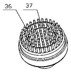
[0034] Embodiment two: see attached Image 6 , the first driving seat 36 and the second driving seat 37 rotate in opposite directions. The drive shaft 35 is provided with a drive gear 351, the drive gear 351 is linked with the second drive seat 37, the drive shaft 351 drives the first drive seat 36 to move through the transmission mechanism 38, and the transmission The mechanism 38 is an engaging gear 383 , the driving gear 351 is engaged with the engaging gear 383 , and the engaging gear 383 is engaged with the first driving seat 36 . Such a structure realizes the reverse rotation of the first driving seat and the second driving seat, so that the cleaning efficiency is higher.
Embodiment 3
[0035] Embodiment three: see attached Figure 7 , 8 , 9, the drive shaft 35 drives the first drive seat 36 to swing through the transmission mechanism 38, and the drive shaft 35 drives the second drive seat 37 to rotate circumferentially. The drive shaft 351 drives the first drive seat 36 to move through the transmission mechanism 38. The transmission mechanism 38 includes a drive plate 384 and a cam 385. The drive plate 384 is provided with a drive block 3841 and is compatible with the cam 385. The chute 3842 is matched, and the first driving seat 36 is provided with a notch groove 361 matching with the driving block 3841 . The drive shaft 35 is linked to the second drive seat 37 , and the cam 385 is linked to the second drive seat 37 . Such a structure realizes that the second driving seat rotates and the first driving seat swings, so that the cleaning efficiency is higher. Of course, it can be known from the combination of Embodiments 1 and 2 in the actual process that t...
PUM
 Abstract
Description
Claims
Application Information
 - R&D Engineer
- R&D Manager
- IP Professional
- Industry Leading Data Capabilities
- Powerful AI technology
- Patent DNA Extraction
Browse by: Latest US Patents, China's latest patents, Technical Efficacy Thesaurus, Application Domain, Technology Topic, Popular Technical Reports.
© 2024 PatSnap. All rights reserved.Legal|Privacy policy|Modern Slavery Act Transparency Statement|Sitemap|About US| Contact US: help@patsnap.com