

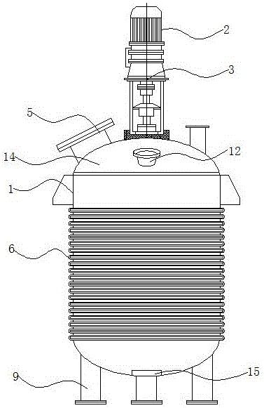
Production of resin with steam heating heat conduction oil circulation heating reaction kettle
A technology of circulating heating and heat-conducting oil, which is applied in chemical/physical/physical-chemical fixed reactors, dissolution, mixers, etc., can solve the problems of occupying the reaction space of the reactor, affecting the reaction efficiency, and reducing the reaction space, etc., to achieve heating The effect is obvious, the reaction space is enlarged, and the heating time is short
- Summary
- Abstract
- Description
- Claims
- Application Information
AI Technical Summary
Problems solved by technology
Method used
Image

Examples
specific Embodiment approach
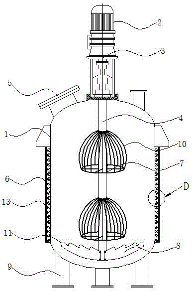
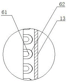
[0019] In order to enable those skilled in the art to better understand the technical solution of the present invention, the technical solution of the present invention will be further described below in conjunction with the accompanying drawings and embodiments. And the steam outer pipe 62 is sleeved, the inner diameter of the steam outer pipe 62 is twice the inner diameter of the heat transfer oil inner pipe 61, and the outer coil 6 is also covered with a layer of heat insulating layer 13, the heat insulating layer 13 is set so that the outer The heat inside the coil 6 is not lost to the outside, and two cage stirrers 7 are arranged on the stirring shaft 4, and the cage stirrer 7 is a hemispherical cage structure surrounded by several ribs 10 , each rib 10 is arc-shaped, the top surface and the bottom surface of the cage stirrer 7 are elliptical, and the ellipse of the upper surface is a quarter of the ellipse of the lower surface, and the ellipses of the upper and lower surf...
PUM
 Abstract
Description
Claims
Application Information