Photovoltaic cleaning robot

A cleaning robot and cleaning mechanism technology, applied in the field of robots, can solve the problems of high water consumption, unsatisfactory, high price, etc., and achieve the effect of reducing the use cost of the product, expanding the applicable occasions, and being easy to use

Inactive Publication Date: 2015-10-21
上海联星股权投资管理有限公司
7 Cites 33 Cited by

AI-Extracted Technical Summary

Problems solved by technology

[0004]At present, the photovoltaic power station cleaning market mainly adopts manual or third-party cleaning mode, which has low cleaning efficiency, high price and high water consumption, which greatly increases the The operation and maintenan...

Method used

Compared with other cleaning methods, the present invention adopts anhydrous cleaning method to solve the problem of water shortage in the western region, and the robot is simple to use in addition, and it is directly placed on the photovoltaic module without the need to perform secondary cleaning on the photovoltaic power station. Refitting can expand the applicable occasions of photovoltaic power plants and reduce the cost of product use. This product adopts the night work mode, which does not affect the normal power generation work of the power station during the day.
[0027] Photovoltaic cleaning robot, photovoltaic module 1 accumulation of dust is cleaned, so as to improve the power generation efficiency of photovoltaic power station. The above-mentioned robot includes a mobile platform mechanism, a driving mechanism, a traveling mechanism, a cable receiving mechanism, and a cleaning mechanism. Photovoltaic module 1 is generally installed at an inclination, and is composed of a row of battery panel arrays. The mobile platform mechanism is connected to the photovoltaic module. As shown in Figure 1, the mobile platform mechanism is a rectangular frame structure composed of two relatively parallel The two horizontal brackets 3 are respectively located at the two ends of the...

Abstract

The invention discloses a photovoltaic cleaning robot. The photovoltaic cleaning robot comprises a mobile platform mechanism, a driving mechanism, a walking mechanism, a cable collecting mechanism and a cleaning mechanism, wherein the mobile platform mechanism spans a photovoltaic module; the driving mechanism is positioned at one side of the mobile platform mechanism, and comprises a first motor; the first motor drives a driving wheel to walk on the surface of the photovoltaic module; the walking mechanism comprises liming wheels walking along the upper and lower side walls of the photovoltaic module, and walking wheels walking along the upper and lower edges of the photovoltaic module; the cable collecting mechanism comprises a second motor; the second motor drives a cable shaft to rotate; a cable on the cable shaft is wound up or payed off around the cable shaft; the cable is connected with the cleaning mechanism, and drives the cleaning mechanism to ascend or descend; the cleaning mechanism comprises a third motor; and the third motor drives a brush to rotate so as to clean ash on the photovoltaic module. The photovoltaic cleaning robot adopts a waterless cleaning mode, is simple in use, is directly placed on the photovoltaic module, widens application places of a photovoltaic power station, and reduces the product use cost.

Application Domain

Technology Topic

Image

  • Photovoltaic cleaning robot
  • Photovoltaic cleaning robot
  • Photovoltaic cleaning robot

Examples

  • Experimental program(1)

Example Embodiment

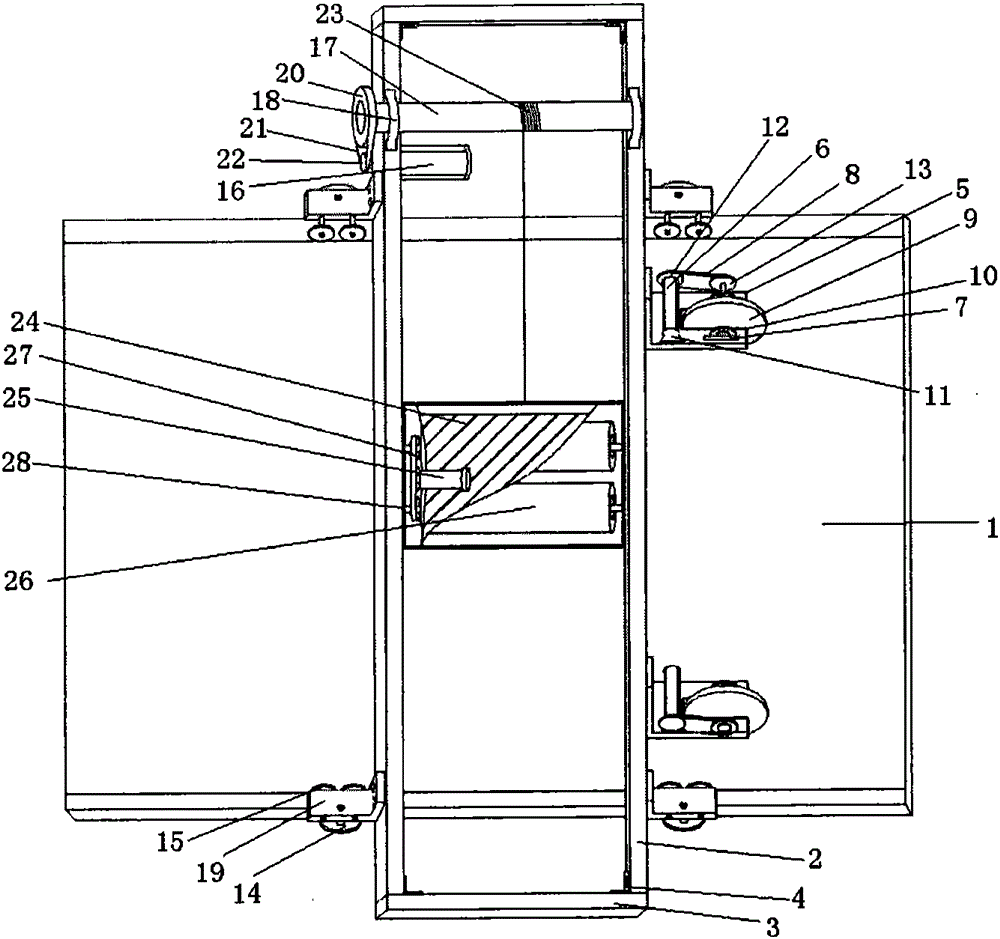
[0027] The photovoltaic cleaning robot cleans the dust accumulation of the photovoltaic module 1 to improve the power generation efficiency of the photovoltaic power station. The above-mentioned robot includes a mobile platform mechanism, a driving mechanism, a walking mechanism, a cable collecting mechanism, and a cleaning mechanism. Photovoltaic module 1 is generally inclined and consists of a row of solar panel arrays. The mobile platform mechanism is connected to the photovoltaic module, such as figure 1 As shown, the mobile platform mechanism is a rectangular frame structure composed of two relatively parallel long brackets 2 and a horizontal bracket 3. The two horizontal brackets 3 are respectively located at the two ends of the two long brackets 2 and the inner sides of the right angle formed between them A connecting piece 4 is provided, and the connecting piece 4 is fixed on the inner side of the long bracket and the horizontal bracket by screws to support and fix the entire frame structure.
[0028] There are two sets of driving mechanisms, both of which are arranged on the outside of a long bracket 2 and located between the walking mechanisms, including the first right angle plate 5, the first motor 6, the first bearing seat 7, the first belt 8 and the driving wheel 9. The right corner of the first right-angled plate 5 is fixed on the outside of the long bracket 2 by screws, and the other right-angled side is provided with an opening slot 10 that opens to the end, and a first bearing seat is installed on the plates on both sides of the opening slot 10 7. The driving wheel 9 is located in the opening slot 10, and is mounted on the first bearing seats 7 on both sides through the axle. A first motor 6 parallel to the long support is fixed on the right-angle side by the motor support 11. The drive shaft of the first motor 6 of the two sets of driving mechanisms and the first driven wheel 13 installed at one end of the wheel shaft are arranged in reverse. The drive shaft of the first motor 6 is provided with a first driving wheel 12, and the first driving wheel 12 passes through a first belt 8. The first driven wheel 13 of the driving wheel axle drives the driving wheel 9 to walk on the array of solar panels of the photovoltaic module 1.
[0029] The walking mechanism has four groups, which are located at the intersection of the long support 2 and the photovoltaic module 1, such as figure 2 , Including a second right-angle plate 19, a limit wheel 14, and a walking wheel 15. The right-angle side of the second right-angle plate 19 is fixed on the outside of the long bracket 2 by screws, and the limit wheel 14 runs along the upper and lower side walls of the photovoltaic module 1. , The traveling wheel 15 walks along the upper and lower edges of the photovoltaic module 1, and its wheel axles are respectively perpendicularly and parallelly penetrated and fixed in another right-angled edge. The four sets of limit wheels 14 realize the limit and travel of the mobile platform mechanism obliquely parallel to the photovoltaic module 1, and the four sets of travel wheels 15 realize the limit and travel of the mobile platform mechanism perpendicular to the photovoltaic module 1. Each set of travel wheels 15 can be equipped with one or two independent wheels.
[0030] Such as Figure 4 , The cable take-up mechanism is located on the upper part of the mobile platform mechanism, including the second motor 16, the cable shaft 17, the second bearing seat 18 and the cable 23. The two second bearing seats 18 are installed on the two long supports 2 oppositely, and the cable shaft 17 The two ends are mounted on two second bearing seats 18, the second driven wheel 20 provided at one end of the cable shaft 17 is connected to the second driving wheel 22 of the second motor 16 through the second belt 21, and the second motor 16 passes through the base 36 is fixed on the underside of the long bracket 2. One end of the cable 23 is fixed on the cable shaft 17 and the other end is connected to the cleaning mechanism. The second motor 16 drives the cable shaft 17 to rotate, and the cable 23 shrinks or unwinds around the cable shaft 17 to drive the cleaning mechanism to rise or fall.
[0031] The cleaning mechanism is located between the two long supports 2, and cleans along the surface of the photovoltaic module 1, such as image 3 , Including a support housing 24, a third motor 25 and two brushes 26, two third bearing seats 28 are respectively provided at both ends of the support housing 24, the two brushes 26 are arranged in parallel, and the two ends are respectively mounted on the third bearing Seat 28. The third motor 25 is installed on the support housing 24, and the same end of the two brushes 26 has a third driven wheel 29. The driving wheel 30 of the third motor 25 is connected to the two third driven wheels 29 through a third belt 27, thereby The two brushes 26 are driven to rotate, so as to clean the surface of the photovoltaic module 1.
[0032] Such as Figure 4 The present invention also includes a power supply device, which can be provided by a built-in battery 32 and a solar panel. The storage battery 32 is installed on the lower side of the upper end of the mobile platform mechanism, and the solar panel charges the battery 32. The photovoltaic panels 35 of the solar panel can be installed on the upper side of the mobile platform mechanism and the upper side of the lower end respectively.
[0033] The present invention can also install a temperature sensor 33 and an image sensor 34 on the support housing 24 of the cleaning mechanism, and the photovoltaic module 1 can be detected as the cleaning mechanism is cleaning.
[0034] The invention mainly develops a cleaning robot, which is driven by a motor to drive the cleaning brush, which rolls on the surface of the photovoltaic module to complete the cleaning work from top to bottom. After the cleaning is completed, the cleaning brush rotates to complete the dust cleaning.
[0035] The cleaning robot is mainly used for cleaning the solar panels of large photovoltaic ground power stations. It is composed of a mobile platform mechanism, a control system, a walking mechanism, a cleaning mechanism, a cable-retracting mechanism, and a power supply device that are connected to the photovoltaic module, and has a certain spanning ability. High-speed rotating electric brushes are used for cleaning. After cleaning from one end of a row of battery panel arrays to the other, it can automatically stop. With battery, it can work at night. The cleaning mechanism has a self-cleaning function.
[0036] Compared with other cleaning methods, the present invention adopts the waterless cleaning method to solve the problem of water shortage in the western region. In addition, the robot is simple to use and is directly placed on the photovoltaic module without the need for secondary modification of the photovoltaic power station. Expand the applicable occasions of photovoltaic power stations and reduce the cost of product use. This product adopts night working mode, which does not affect the normal power generation work of the power station during the day.
[0037] Taking a 10MW power station in the Northwest region as an example, its theoretical annual power generation is about 17 million kWh. Calculated according to the converted power generation efficiency of 80%, the annual income is about 13.6 million yuan. Using traditional cleaning methods, cleaning 10 times a year, the efficiency will drop by 10%-20%, and the minimum loss will be 1.36 million yuan. Using robot cleaning, the appropriate cleaning frequency can increase the efficiency by 5%-10%, and the minimum increase will be 680,000 yuan. For different cleaning methods, the income difference between the two is at least 15%, and the income difference is 2.04 million yuan/year. In addition, clean the surface of the module in time to prevent blocking and hot spot effects, and improve the service life of photovoltaic modules. In short, cleaning the photovoltaic modules every day will greatly benefit the performance and investment income of the photovoltaic system.
[0038] The above content is merely an example and description of the structure of the present invention. Those skilled in the art make various modifications or additions to the specific embodiments described or substitute similar methods, as long as they do not deviate from the structure of the invention or Anything beyond the scope defined by the claims shall belong to the protection scope of the present invention.

PUM

no PUM

Description & Claims & Application Information

We can also present the details of the Description, Claims and Application information to help users get a comprehensive understanding of the technical details of the patent, such as background art, summary of invention, brief description of drawings, description of embodiments, and other original content. On the other hand, users can also determine the specific scope of protection of the technology through the list of claims; as well as understand the changes in the life cycle of the technology with the presentation of the patent timeline. Login to view more.

Similar technology patents

Dimming method for infrared camera

Owner:SKY LIGHT ELECTRONICS SHENZHEN

Classification and recommendation of technical efficacy words

  • Energy saving
  • Easy to use

Laser assisted total joint arthroplasty

InactiveUS20090234360A1Easy to useNon-surgical orthopedic devicesSurgical sawsLaser assistedLaser guidance
Owner:ALEXANDER VLADIMIR

System, method, and apparatus for settlement for participation in an electric power grid

ActiveUS8583520B1Communication securityEasy to useLevel controlCoin-freed apparatusNetwork managementGrid operator
Owner:CAUSAM ENERGY INC
Why Eureka
Try Eureka