Stacking mold

A laminated mold and cavity technology, applied in the field of injection molding equipment, can solve the problems of unbalanced pressure in the front and rear cavities, difficult material sealing, complicated flow channels, etc., and achieve simple and efficient cavity structure, pressure balance, and simple flow channel structure. Effect

Active Publication Date: 2015-10-21
GUANGDONG WEIDA INTELLIGENT EQUIP CO LTD
View PDF4 Cites 5 Cited by
  • Summary
  • Abstract
  • Description
  • Claims
  • Application Information

AI Technical Summary

Problems solved by technology

Due to the complex and long flow path of the existing laminated mold, the material injected from the main feed port needs to pass through the parting surface and be evenly distributed between the two layers of cavities, resulting in the problem of unbalanced pressure between the front and rear cavities
In addition, since the material is injected from the module on one side of the mold, there is a problem that the material is difficult to seal when the mold is opened

Method used


Image

  • Stacking mold
  • Stacking mold
  • Stacking mold

Examples


Embodiment Construction

[0020] In order to make the purpose, technical solutions and advantages of the embodiments of the present invention clearer, the technical solutions in the embodiments of the present invention will be clearly and completely described below in conjunction with the drawings in the embodiments of the present invention. Obviously, the described embodiments It is a part of embodiments of the present invention, but not all embodiments. Elements and features described in one drawing or one embodiment of the present invention may be combined with elements and features shown in one or more other drawings or embodiments. It should be noted that representation and description of components and processes that are not related to the present invention and known to those of ordinary skill in the art are omitted from the drawings and descriptions for the purpose of clarity. Based on the embodiments of the present invention, all other embodiments obtained by persons of ordinary skill in the ar...


PUM


Abstract

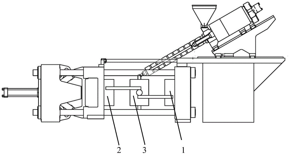
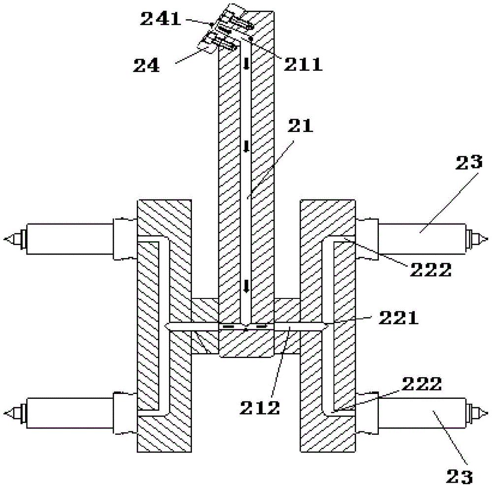
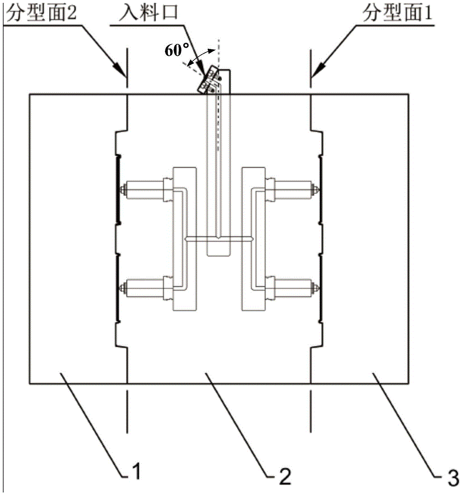
The invention relates to a stacking mold which is provided with a fixed mold block, a movable mold block and a middle mold block, wherein the middle mold block is arranged between the fixed mold block and the movable mold block, and the movable mold block and the middle mold block move to the fixed mold block until the middle mold block and the fixed mold block form a first mold cavity and the movable mold block and the middle mold block form a second mold cavity; the stacking mold further comprises an injection molding flow channel, wherein the central axis of a main body of a main flow channel of the injection molding flow channel is arranged in a central plane, which is perpendicular to the direction of the moving axis of the movable mold block, of the middle mold block. According to the stacking mold, materials enter the injection molding flow channel through the middle mold block without penetrating through a parting surface, so that the pressure of each mold cavity is balanced, and additionally, the problem of seal leakage of the materials during mold opening is avoided.

Description

technical field [0001] The invention relates to the field of injection molding equipment, in particular to a laminated mold. Background technique [0002] The mold of the traditional horizontal injection molding machine has only one cavity, and each time the mold is opened and closed, only one layer of products can be produced, and the production efficiency is low. For this reason, people design " laminated mold ", for example, CN203792627U, CN201346830Y all disclose laminated mold, and it comprises movable module, middle module, fixed module arranged in order from front to back in structure, and the difference between movable module and middle module The first layer of cavity is formed between the middle module and the fixed module, and the second layer of cavity is formed between the middle module and the fixed module. Usually, the general feed port of the mold is set on the fixed module, and the material is poured into each cavity through horizontal injection. Due to th...

Claims


Application Information

Patent Timeline
IPC IPC(8): B29C45/26B29C45/32B29C45/27
CPCB29C45/26B29C45/27B29C45/32B29C45/2602B29C45/322
Inventor 陈寒锐刘信
Owner GUANGDONG WEIDA INTELLIGENT EQUIP CO LTD
Why Eureka
Try Eureka