
A brake valve assembly

A combined body and brake valve technology, which is applied in the field of brake valves, can solve the problems of increasing the driver's operation action, increasing the driver's burden, braking tires, etc., to improve reliability and safety, simplify the brake system, and facilitate use and maintenance Effect

Inactive Publication Date: 2017-11-03
XIAN AVIATION BRAKE TECH
View PDF5 Cites 0 Cited by
  • Summary
  • Abstract
  • Description
  • Claims
  • Application Information

AI Technical Summary

Problems solved by technology

The disadvantage of using this take-off line brake system is that when the aircraft brakes on the take-off line, the driver needs to pull the take-off line brake switch with his hand instead of stepping on the brake with his foot, which does not conform to the ergonomics principle and increases the driver's operation. , at the critical moment when the plane takes off, it will virtually increase the burden on the pilot
In addition, during the landing process of the aircraft, due to human negligence, mechanical or other factors, the brake switch of the take-off line is turned on by mistake, which will cause accidents such as brake and burst tires.

Method used


Image

  • A brake valve assembly
  • A brake valve assembly

Examples


Embodiment 1

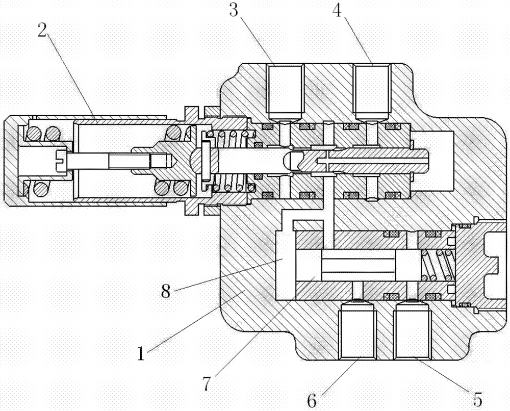
[0019] see figure 1 . This embodiment is a brake valve assembly, including: a housing 1 , a brake pressure reducing valve 2 and a hydraulically controlled switching valve 7 . The brake pressure reducing valve 2 and the hydraulic control switching valve are respectively installed in the brake pressure reducing valve chamber and the hydraulic control switching valve chamber on the housing 1 . There are four hydraulic ports on the housing 1, which are the oil return port 3, the first pressure supply port 4, the second pressure supply port 5 and the brake port 6, and the hydraulic ports are respectively connected with the hydraulic lines of the aircraft brake system , wherein: the oil return port 3 of the brake valve assembly is connected to the oil return pipeline of the aircraft through a hydraulic nozzle and a conduit, and leads to the oil return tank; the first pressure supply port 4 of the brake valve assembly is connected to the aircraft normally through a hydraulic nozzle ...

Embodiment 2

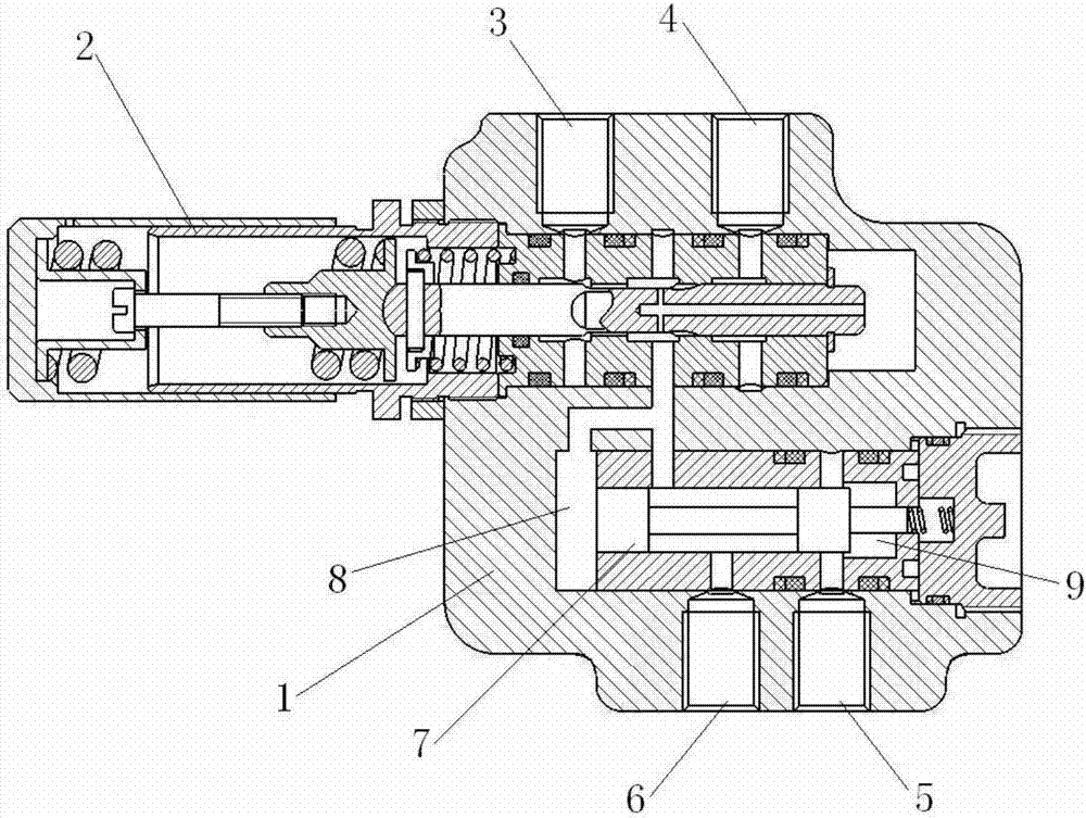
[0040] see figure 2 . This embodiment is a brake valve assembly, which includes a housing 1 , a brake pressure reducing valve 2 and a hydraulic control switching valve 7 . The brake pressure reducing valve 2 and the hydraulic control switching valve are respectively installed in the brake pressure reducing valve chamber and the hydraulic control switching valve chamber on the housing. There are four hydraulic ports on the housing 1, which are the oil return port 3, the first pressure supply port 4, the second pressure supply port 5 and the brake port 6, and the hydraulic ports are respectively connected with the hydraulic lines of the aircraft brake system , wherein: the oil return port 3 of the brake valve assembly is connected to the oil return pipeline of the aircraft through a hydraulic nozzle and a conduit, and leads to the oil return tank; the first pressure supply port 4 of the brake valve assembly is connected to the aircraft normally through a hydraulic nozzle and c...


PUM


Abstract

The invention discloses a brake valve assembly. A brake pressure reducing valve is arranged in a brake pressure reducing valve cavity of a casing, a liquid-controlled conversion valve is arranged in a liquid-controlled conversion valve cavity of the casing, and the brake pressure reducing valve cavity and the liquid-controlled conversion valve cavity are communicated; the outer end of an oil return opening, the outer end of a first pressure supply opening, the outer end of a second pressure supply opening, and the outer end of a brake opening are separately connected with a hydraulic pipeline of a brake system of an aircraft; the inner end of the oil return opening, and the inner end of the first pressure supply opening are separately communicated with the brake pressure reducing valve cavity; the inner end of the second pressure supply opening is communicated with air inlets of the liquid-controlled conversion valve, and the inner end of the brake opening is communicated with an oil outlet of the liquid-controlled conversion valve. When the brake valve assembly disclosed by the invention is used in normal braking, the pressure of a pressure supply source of the brake system is reduced to needed brake pressure; when the aircraft is braked at a take-off line, the pressure of the pressure supply source of the brake system is directly output without reduction; a normal braking function and a braking function at the take-off line can be realized through the foot control of a pilot. According to the brake valve assembly disclosed by the invention, the brake system is simplified, and the reliability and the safety of the brake system of the aircraft are improved. In addition, independent accessories are integrated in the brake valve assembly disclosed by the invention, and the brake valve assembly is designed and manufactured according to modularization, so that the brake valve assembly is convenient to use and maintain.

Description

technical field [0001] The invention relates to an aircraft wheel hydraulic brake system, in particular to a brake valve with decompression function and non-decompression direct output. Background technique [0002] The brake valve is the basic component of the aircraft brake system. This brake valve is actually a variable pressure reducer. During normal braking, the driver usually manipulates the brake valve through the pedal mechanism to reduce the high-pressure hydraulic pressure provided by the hydraulic brake system supply source to the required brake pressure, and output it to the wheel brake device for braking. Due to the increase of aircraft take-off thrust, especially the use of carbon brakes, the brake pressure required for take-off line braking has doubled (some have exceeded twice the maximum normal brake pressure), and the brake pressure output by the brake valve of the normal brake system cannot meet the requirements. Some aircraft are equipped with a special...

Claims


Application Information

Patent Timeline
Patent Type & Authority Patents(China)
IPC IPC(8): B60T15/04B64C25/44
CPCB60T15/04B64C25/44
Inventor 何永乐郭育秦
Owner XIAN AVIATION BRAKE TECH
Learn More