
A side fastening device for tin bath bottom brick with tooth meshing

A technology of tin bath bottom bricks and fastening devices, which is applied in the field of tin bath forming equipment, and can solve problems such as threaded fasteners that cannot be fastened

Active Publication Date: 2017-03-29
(CNBM) BENGBU DESIGN & RES INST FOR GLASS IND CO LTD
View PDF5 Cites 0 Cited by
  • Summary
  • Abstract
  • Description
  • Claims
  • Application Information

AI Technical Summary

Problems solved by technology

[0005] The purpose of the present invention is to solve the technical problem that the threaded fasteners in the prior art cannot be fastened from one side, and further propose a side fastening device for tin bath bottom bricks with tooth meshing

Method used


Image

  • A side fastening device for tin bath bottom brick with tooth meshing
  • A side fastening device for tin bath bottom brick with tooth meshing
  • A side fastening device for tin bath bottom brick with tooth meshing

Examples


Embodiment 1

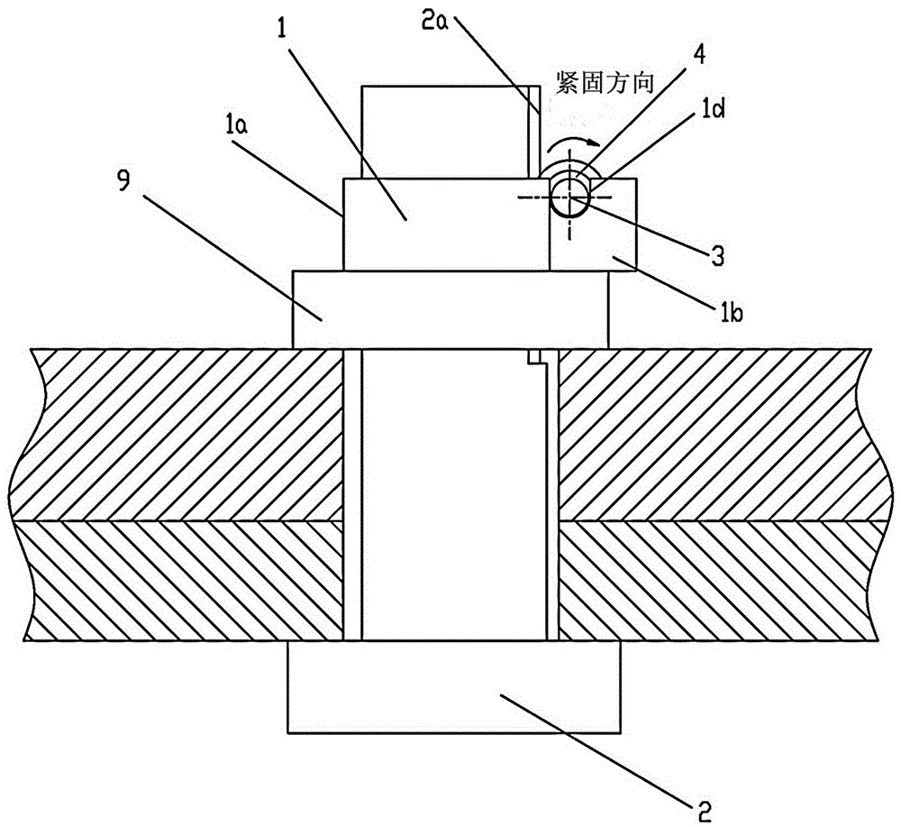
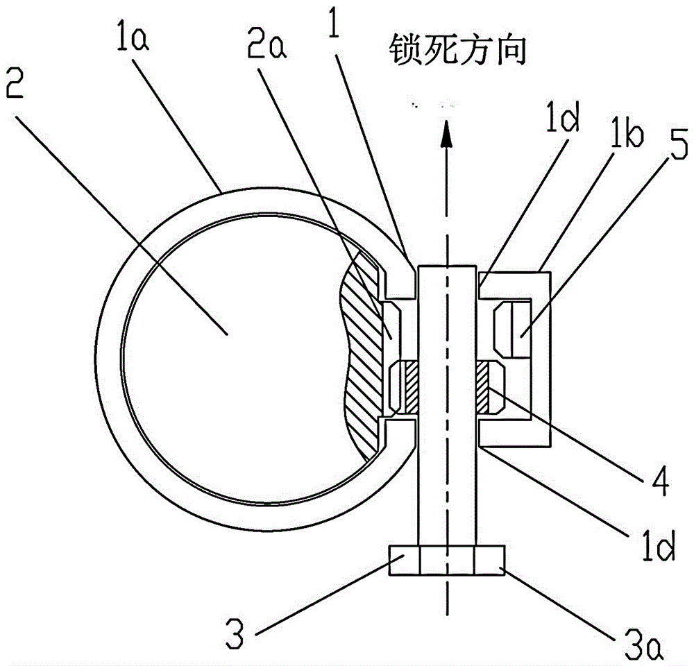
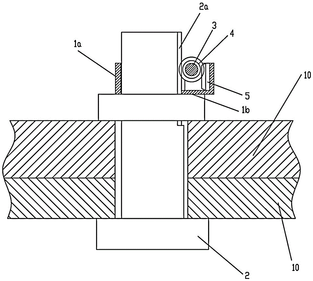
[0022] A toothed tin bath bottom brick side fastening device such as figure 1 As shown, it includes a pair of movable parts 10 to be fastened, and the movable socket fastening rod 2 on the fastened parts 10, the cross section of the fastening rod 2 can be set to square, circular and other shapes that are easy to process and manufacture , choose a circle here, and set a section of rack teeth 2a arranged along the axis on one side of the fastening rod 2 . One end of the fastening rod 2 is sleeved with an annular pressure block 9 that is press-fitted with the end face of the fastener 10 to be fastened, and the end of the fastening rod 2 is sleeved with a compression member 1 that is press-fitted with the other end face of the press block 9 .

[0023] Such as figure 2 and image 3 , the compression piece 1 is provided with a compression sleeve 1a that slides and fits with the peripheral surface of the tightening rod 2, the compression sleeve 1a is pressed against one end surfac...

Embodiment 2

[0029] A toothed tin bath bottom brick side fastening device such as Figure 5 As shown, the bottom plate 7 of the tin bath is included, and a group of fastening rods 2 are welded on the bottom plate 7 of the tin bath. One side of the fastening rod 2 is provided with rack teeth 2a arranged along the axis. A group of refractory tin bath bottom bricks 6 are laid on the tin bath bottom plate 7, and two fastening holes 6a whose axes are perpendicular to the tin bath bottom plate 7 are arranged on each tin bath bottom brick 6, and the fastening holes 6a are a port and the tin bath bottom brick 6. A blind hole connected to the bottom surface of the bottom brick 6 . The tin bath bottom brick 6 is provided with horizontal side tightening holes 6b respectively connected with the corresponding fastening holes 6a, and the side tightening holes 6b are blind holes with one port communicating with the side of the tin bath bottom brick 6 .

[0030] The corresponding fastening rod 2 is slee...


PUM


Abstract

The invention relates to a lateral fastening device in tooth meshing for a tin bath bottom brick. The lateral fastening device comprises a component (10) to be fastened and is characterized in that a fastening rod (2) is connected to the component (10) to be fastened in a sleeving manner, and a group of rack wheel teeth (2a) are arranged on one side of the fastening rod (2); the fastening rod (2) is connected with a pressing component (1); the pressing component (1) comprises a pressing sleeve (1a), wherein the pressing sleeve (1a) is connected with the periphery surface of the fastening rod (2) in a sliding and sleeving manner and matched with the component (10) in a pressing and fastening manner; a fastening casing (1b) is arranged on the outer side of the pressing sleeve (1a); a transverse rotating hole (1d) is formed in the fastening casing (1b), a rotating shaft (3) is connected to the inner part of the rotating hole (1d), one end of the rotating shaft (3) is connected with a cap cover (3a), and a gear (4) meshed with the rack wheel teeth (2a) is fixedly connected to the rotating shaft (3); an inner cavity of the fastening casing (1b) is connected with a fixed rack (5). Through the adoption of the technical scheme, the purpose of laterally fastening a fastener is realized, and after the lateral fastening tool disclosed by the invention is adopted by the tin bath bottom brick and a tin bath bottom plate, a fastening hole is not formed in the using surface of the tin bath bottom brick any longer.

Description

technical field [0001] The invention relates to the technical field of glass production equipment, in particular to tin bath forming equipment in the float glass production process. Background technique [0002] Threaded fasteners include bolts and nuts. The threaded fasteners are pre-tightened by applying a relative force couple to the nut or bolt. When the force couple is applied, a certain amount of movement space is required. If there is no movement space, the threaded fasteners cannot be pre-tightened. [0003] In the production process of float flat glass, the tin bath is a forming equipment containing high-temperature tin liquid, and the tin bath is a steel shell lined with refractory bricks. The bottom of the tin bath includes a tin bath bottom plate connected with a layer of tin bath bottom bricks made of a refractory material. In order to prevent the bottom brick of the tin bath from being floated by the tin liquid, the following connection method is adopted: the ...

Claims


Application Information

Patent Timeline
Patent Type & Authority Patents(China)
IPC IPC(8): C03B18/18
Inventor 马永张治民
Owner (CNBM) BENGBU DESIGN & RES INST FOR GLASS IND CO LTD
Learn More