Cloth dyeing machine of cloth lifting wheel-free cloth conveying system

A conveying system and a cloth-lifting wheel technology, applied in the field of dyeing machines, can solve the problems of scratches on the cloth surface, uneven dyeing of the cloth, high energy consumption of the cloth-lifting wheel cloth conveying device, etc. uniform effect

Active Publication Date: 2015-10-21
HANGZHOU DONGLIN DYEING & FINISHING MACHINERY
View PDF4 Cites 4 Cited by
  • Summary
  • Abstract
  • Description
  • Claims
  • Application Information

AI Technical Summary

Problems solved by technology

[0003] The invention aims at the fact that in the prior art, the cloth is prone to creases and scratches during the conveying process, there is a speed difference between the cloth lifting wheel belt cloth and the nozzle belt clot

Method used


Image

  • Cloth dyeing machine of cloth lifting wheel-free cloth conveying system
  • Cloth dyeing machine of cloth lifting wheel-free cloth conveying system
  • Cloth dyeing machine of cloth lifting wheel-free cloth conveying system

Examples


Embodiment 1

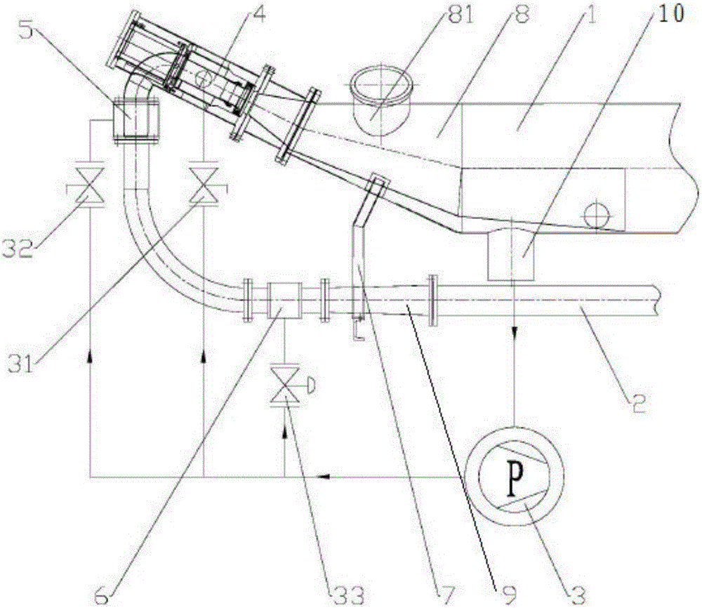
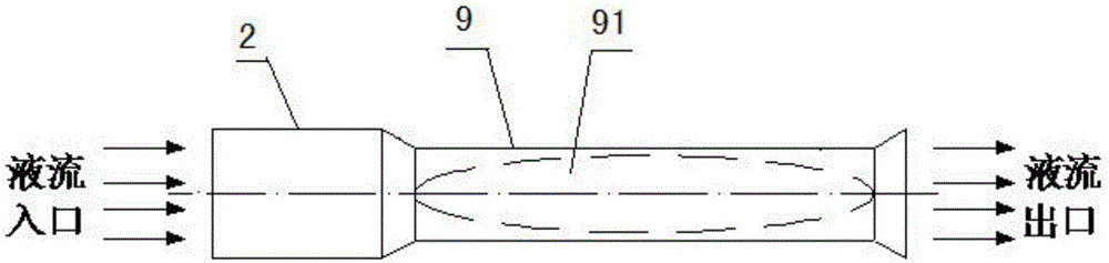
[0023] The cloth dyeing machine without the cloth conveying system, as shown in the figure, includes the main cylinder 1, the cloth guide pipe 2 and the pump 3, the main cylinder 1 is connected with the pump 3, and the main nozzle 4 is arranged on the cloth guide pipe 2 , cloth feeding nozzle 5 and reverse thrust nozzle 6, cloth guide pipe 2 is connected with main cylinder 1 through main nozzle 4, cloth guide pipe 2 is installed with cloth feeding nozzle 5 and reverse thrust nozzle 6 sequentially along the flow direction, main nozzle 4 and the pump 3 are provided with a first valve 31, a second valve 32 is provided between the cloth feeding nozzle 5 and the pump 3, a third valve 33 is provided between the reverse thrust nozzle 6 and the pump 3; There is a tapered barrel body 8, which reduces the height of the cloth to the main nozzle 4, thereby reducing the work to be done by the main nozzle 4 to lift the cloth. The tapered barrel body 8 is equipped with a support frame 7, The...

Embodiment 2

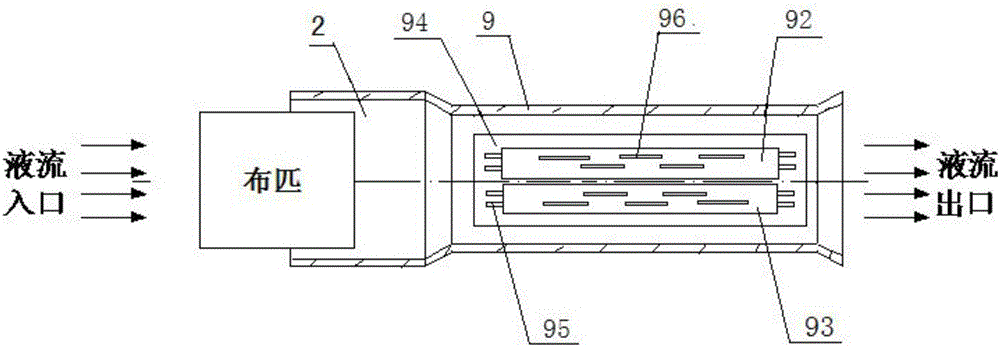
[0025] With embodiment 1, the difference is that the setting of the elliptical groove 91 in the anti-rotation pipe 9 is changed to the left belt 92 and the right belt 93 located on the bottom of the inner surface of the anti-rotation pipe 9, and the left belt 92 and the right belt 93 are all perpendicular to the The direction of cloth movement is turned outward. Both the outer surfaces of the left belt 92 and the right belt 93 are provided with convex strips 96 . The bottom of the anti-rotation pipe 9 inner surface is equipped with a positioning plate 94, four rolling shafts 95 are installed on the positioning plate 94, the left belt 92 is installed on the two rolling shafts 95, and the right belt 93 is installed on the other two rolling shafts 95 , the left belt 92 and the right belt 93 are all driven by the rolling shaft 95 to run. All have a rolling shaft 95 to be connected with motor in the rolling shaft 95 that is connected with left belt 92 and right belt 93. The left ...


PUM


Abstract

The invention relates to a cloth dyeing machine and discloses a cloth dyeing machine of a cloth lifting wheel-free cloth conveying system. The cloth dyeing machine comprises a main cylinder body (1), a cloth guide pipe (2) and a pump (3), wherein the main cylinder body (1) is connected with the pump (3); a main nozzle (4), a cloth-feeding nozzle (5) and a backpushing nozzle (6) are mounted on the cloth guide pipe (2); the cloth guide pipe (2) is connected with the main cylinder body (1) via the main nozzle (4); the cloth guide pipe (2) is orderly provided with the cloth-feeding nozzle (5) and the backpushing nozzle (6) along a flow liquid direction; and a cloth discharging end of the cloth guide pipe (2) is provided with an anti-rotating pipe (9) preventing the cloth rotating. Tension during the cloth conveying can be effectively avoided by the use of the main nozzle, the cloth-feeding nozzle and the backpushing nozzle; and with the anti-rotating pipe in the anti-rotating device, the cloth can be expanded and flattened in the cloth guide pipe, so even dyeing can be achieved.

Description

technical field [0001] The invention relates to a cloth dyeing machine, in particular to a cloth dyeing machine without a cloth conveying system with a cloth lifting wheel. Background technique [0002] Generally, cloth dyeing machines on the market use the cloth lifting wheel to transfer the cloth for printing and dyeing, but this kind of cloth dyeing machine has the following disadvantages: 1. During the process of conveying the cloth by the cloth lifting wheel, the cloth is prone to creases and scratches on the cloth surface; 2. .The speed difference between the belt of the cloth lifting wheel and the cloth of the cloth feeding nozzle will cause extra tension in the cloth during the transmission process; 3. The cloth lifting wheel is driven by the cloth lifting motor, which will consume a lot of electric energy; 4. The cloth lifting Leakage of the wheel mechanical seal will cause pressure loss; 5. The cloth is prone to rotation and knotting in the cloth guide tube, result...

Claims


Application Information

Patent Timeline
IPC IPC(8): D06B3/28D06B3/34
CPCD06B23/08
Inventor 陈芳萍
Owner HANGZHOU DONGLIN DYEING & FINISHING MACHINERY
Why Eureka
Try Eureka