Combined component

A combination of components, a pair of technology, applied in the direction of building construction, construction, etc., can solve the problems of large gaps in component cross-section shapes, inflexible versatility, and long construction periods, achieving high structural rigidity, saving installation time, and reducing transportation costs. and the effect of installation costs

Active Publication Date: 2015-10-21
北京海东蓝涛洁净工程技术有限公司
View PDF8 Cites 7 Cited by
  • Summary
  • Abstract
  • Description
  • Claims
  • Application Information

AI Technical Summary

Problems solved by technology

Due to the large section size and self-heavyness of the beam-column components of civil engineering, large-scale construction machinery and on-site pouring construction are required, resulting in a relatively long construction period
Although the steel beam-column components have a strong load-bearing capacity, they are also heavy, and large-scale construction machinery is also required during construction.
In addition, the cross-sectional shapes of the two types of beams and columns are relatively different, and the versatility is not flexible enough

Method used


Image

  • Combined component
  • Combined component
  • Combined component

Examples


Embodiment 1

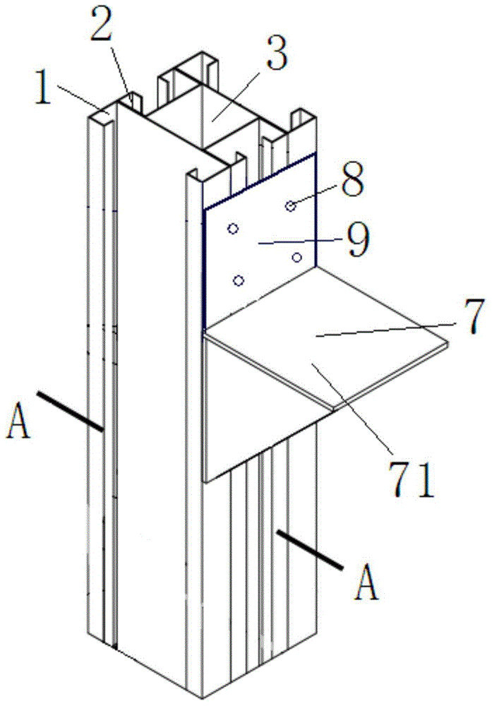
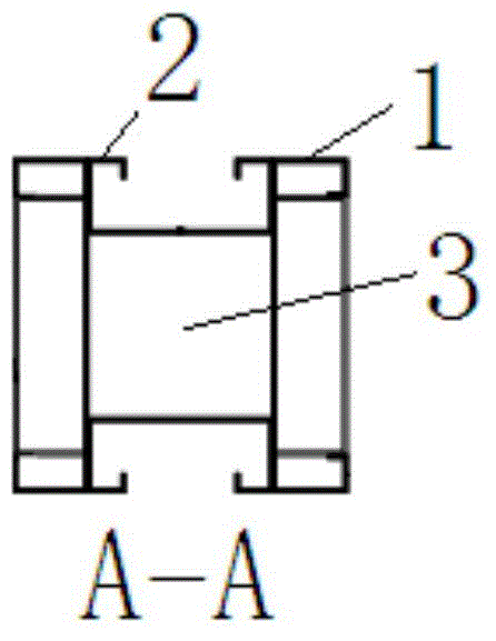
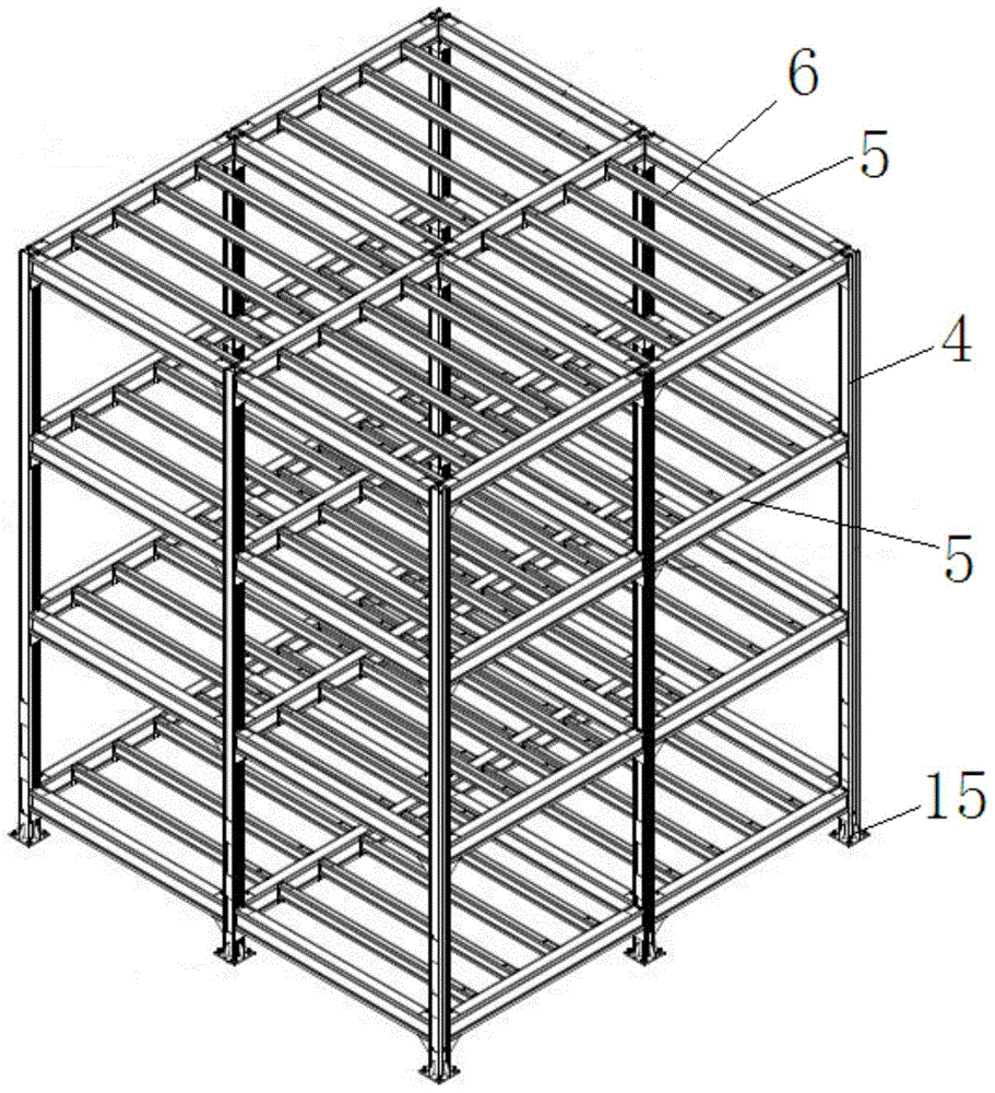
[0025] Such as figure 1 , Figure 4 As shown, when the present invention is used as a column 4 and a main beam 5, several corbels 7 and connecting plates 9 with mounting holes 8 are welded at intervals along the length direction of the section steel on the column 4 and the main beam 5 . The supporting surfaces 71 of the corbels 7 arranged at intervals along the longitudinal direction of the profiled steel on the column 4 are perpendicular to the longitudinal direction of the profiled steel; parallel. Just can distinguish column 4 or girder 5 according to the difference between the support surface 71,72 of corbel 7 and profiled steel length direction like this, if corbel 7 is not set on profiled steel simultaneously, just can judge that this component is secondary beam 6 (as image 3 , Figure 5 shown).

Embodiment 2

[0027] Such as Figure 4 , Figure 5 As shown, when the present invention is used as the main beam 5 or the secondary beam 6, since its two ends need to be connected with two adjacent columns or two main beams, it is necessary to weld the seals with mounting holes 10 at the two ends of the present invention respectively. head board11. At the same time, when the secondary beam 6 is installed on the main beam 5, the secondary beam 6 is located on the supporting surface 72 of the corbel 7, and is fixed through the mounting holes 8, 10 of the connecting plate 9 and the head plate 11 by bolts, so the secondary beam 6 The top of the beam 6 will be flush with the top of the main beam 5. According to this feature, it can be judged whether the secondary beam 6 is matched with the main beam 5; in addition, it can also be based on the installation of the connecting plate 9 and the head plate 11 on the column 4 and the main beam 5, or between the main beam 5 and the secondary beam 6. T...

Embodiment 3

[0029] Such as Image 6 Shown, when the present invention is used for making multi-storey building, need column 4 lengthening, like this, can weld a plate (not shown in the figure) in the column 4 upper cavity 3 of lower floor, support a set of Pipe 12; Weld the sleeve pipe 12 and the port connection of the lower column 4 cavity 3 into one, and weld a transverse channel steel reinforcement plate 13 at the notches at the ends of the upper and lower columns 4 at the same time. Both the top and the bottom of the steel reinforcing plate 13 are provided with connection holes 14 . When the two columns 4 are lengthened and connected, as long as the cavity 3 at the bottom of the upper column 4 is placed on the casing 12 at the top of the lower column 4 to join the two columns 4, then use each bolt to pass through each of the upper and lower opposite sides in turn. The four connection holes 14 provided on the transverse channel steel reinforcing plate 13 are fixed with nuts; and so on...


PUM


Abstract

The invention relates to a combined component which is characterized in that the component comprises two pairs of box iron arranged at intervals and provided with inwards-turned edges, the cold-formed thin walls of the box iron are in a C shape, two wings of one pair of box iron are welded to the backs of two webs of the other pair of box iron, profile steel is formed, the inner surface of the profile steel is a through strip-shaped cavity, each side of the outer surface of the profile steel is provided with a through strip-shaped groove opening, and the section of the cavity is square or rectangular; a plurality of brackets and connection plates with mounting holes are welded to the profile steel at intervals, the profile steel serves as a stand column when the supporting faces of the brackets are perpendicular to the length direction of the profile steel, serves as a main girder when the supporting faces of the brackets are parallel to length direction of the profile steel and serves as an auxiliary girder when no bracket and corresponding connection plate are arranged on the profile steel. The combined component is made with a hot galvanizing thin-wall cold-rolled steel sheet as a base material, can be widely applied to building structures and can serve as the stand column as well as the girders.

Description

technical field [0001] The invention relates to a building component, in particular to a composite component used for a building load-bearing structure. Background technique [0002] The existing building structures are mainly divided into civil structures and steel structures. Due to the large section size and self-heavyness of civil engineering beam-column components, large-scale construction machinery and on-site pouring construction are required, resulting in a relatively long construction period. Although the steel beam-column components have a strong bearing capacity, they are also heavy, and large construction machinery is also required during construction. In addition, the cross-sectional shapes of these two types of beams and columns are quite different, and the versatility is not flexible enough. Contents of the invention [0003] In view of the above problems, the object of the present invention is to provide a composite member with good bearing performance an...

Claims


Application Information

Patent Timeline
Patent Type & Authority Applications(China)
IPC IPC(8): E04B1/58E04B1/19
Inventor 程树斌刘全付
Owner 北京海东蓝涛洁净工程技术有限公司
Why Eureka
Try Eureka