A lubricating flow guide structure for a dual-clutch transmission

A dual-clutch, clutch technology, applied in the direction of gear lubrication/cooling, transmission parts, components with teeth, etc., can solve the problem that the shaft end bearing and the center oil passage are not considered to supply oil separately, and it is not suitable for special dual-clutch transmissions. The structure and the source of lubricating oil are not explained, so as to achieve the effect of simple structure, avoiding pressure lubricating oil passage, and convenient processing

Active Publication Date: 2017-03-01
CHONGQING CHANGAN AUTOMOBILE CO LTD
View PDF7 Cites 2 Cited by
  • Summary
  • Abstract
  • Description
  • Claims
  • Application Information

AI Technical Summary

Problems solved by technology

[0003] The first type is to lubricate the gears, bearings and other lubricating points by means of gear oil stirring. However, due to the high installation position of some lubrication points, it is difficult to provide enough lubricating oil for these points by means of gear oil stirring.
[0004] The second type is to use the oil pump to pump oil to the nozzle of the oil pipe to spray oil to lubricate each lubrication point of the transmission. Although this type of method can achieve a better lubricating effect, it needs to install an oil pump and an oil injection device, which is cumbersome to manufacture and use.
However, this device does not consider the separate oil supply to the shaft end bearing and the central oil passage, and the source of the lubricating oil is not explained, so it is not suitable for the special structure of the dual clutch transmission

Method used


Image

  • A lubricating flow guide structure for a dual-clutch transmission
  • A lubricating flow guide structure for a dual-clutch transmission

Examples


Embodiment Construction

[0017] The present invention will be further described below in conjunction with the accompanying drawings.

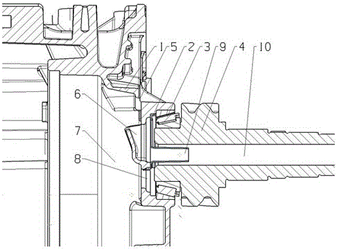
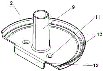
[0018] see figure 1 The shown lubricating and diverting structure of a dual clutch transmission includes a clutch case 1, a shaft end bearing 3 that is connected to the clutch case and corresponds to the clutch installation cavity 7, and a drive shaft 4 whose left end is mated with the shaft end bearing , its prominent substantive features are: the transmission shaft 4 is provided with a central oil passage 10 passing through the axis line and a plurality of small lubricating holes (not shown in the figure) communicating with the central oil passage, so that the lubricating oil passes through many The two lubricating holes respectively reach the parts that need to be lubricated; on the left side of the shaft end bearing 3, there is a guide member 2, which communicates with the central oil passage 10 of the transmission shaft 4; The upper part of the flow guiding membe...


PUM


Abstract

The invention relates to a lubrication and diversion structure of a dual-clutch transmission. The lubrication and diversion structure comprises a clutch casing, a shaft end bearing which is connected to the clutch casing in a matching manner and corresponds to a clutch installation cavity and a transmission shaft, and the left end of the transmission shaft is connected with the shaft end bearing in a matching manner. The lubrication and diversion structure is characterized in that the transmission shaft is provided with a central oil duct which penetrates through the shaft axis of the transmission shaft and a plurality of lubrication small holes communicated with the central oil duct, lubricating oil reaches positions which need to be lubricated through the plurality of lubrication small holes, a diversion member is arranged at the left side of the shaft end bearing, the diversion member is communicated with the central oil duct of the transmission shaft, a casing upper shunting groove is arranged next to the upper part of the diversion member, a casing lower upper shunting groove is arranged next to the lower part of the diversion member. The lubrication and diversion structure of the dual-clutch transmission can satisfy the oil return requirement of the dual clutch, and also can satisfy the shafting lubrication requirement, the lubricating system is simplified, and the lubrication efficiency is improved.

Description

technical field [0001] The invention belongs to the technical field of lubrication, and in particular relates to a lubrication flow guiding structure of a double clutch transmission. Background technique [0002] At present, mechanical gear transmissions have multiple gear meshing points, rotating bearings, clutches and other parts that need to be lubricated. Sufficient lubricating oil must be provided for each part that needs to be lubricated to ensure that the transmission system is in a normal working state. The current transmission lubrication system is basically divided into two categories: [0003] The first type is to lubricate the gears, bearings and other lubricating points by means of gear oil stirring. However, due to the high installation position of some lubrication points, it is difficult to provide enough lubricating oil for these points by means of gear oil stirring. [0004] The second type is to use the oil pump to pump oil to the nozzle of the oil pipe to...

Claims


Application Information

Patent Timeline
Patent Type & Authority Patents(China)
IPC IPC(8): F16H57/04
CPCF16H57/0423F16H57/0426F16H2700/02
Inventor 刘波夏灵王鑫刘诗王厚勇
Owner CHONGQING CHANGAN AUTOMOBILE CO LTD
Why Eureka
Try Eureka