Connector shear strength testing device

A technology of shear strength and testing device, which is applied in the direction of applying stable shear force to test the strength of materials, etc., which can solve the problems of difficult processing and manufacturing, time-consuming testing, and falling off of upper and lower clamps, and achieve the effect of easy processing and manufacturing

Inactive Publication Date: 2015-10-21
HENAN MECHANICAL & ELECTRICAL ENG COLLEGE
View PDF10 Cites 3 Cited by
  • Summary
  • Abstract
  • Description
  • Claims
  • Application Information

AI Technical Summary

Problems solved by technology

The test is time-consuming, and the material is easy to fall off from the upper and lower clips
[0005] The "Joint Shear Strength Test Fixture" invented by Northwestern Polytechnical University is attached Figure 4 , the ferrule

Method used


Image

  • Connector shear strength testing device
  • Connector shear strength testing device
  • Connector shear strength testing device

Examples


Embodiment Construction

[0018] Below in conjunction with accompanying drawing and embodiment the utility model is further described.

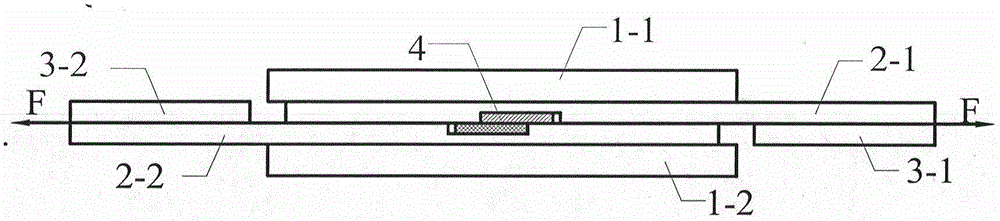
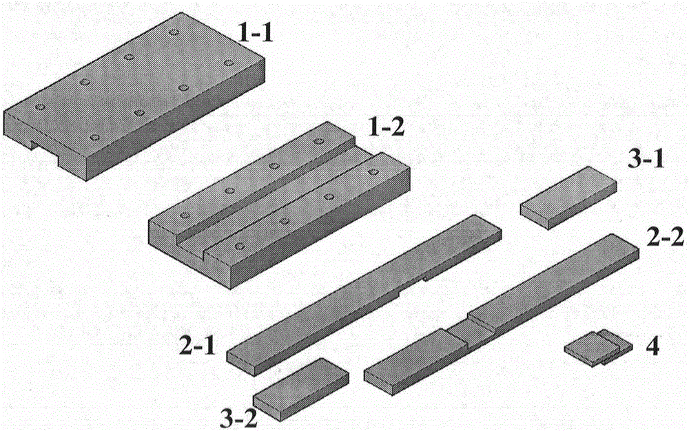
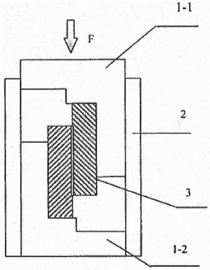
[0019] Such as figure 1 and figure 2 , the present invention comprises guide rail 1-1, guide rail 1-2, pull rod 2-1, pull rod 2-2, backing plate 3-1, backing plate 3-2, and guide rail 1-1 and guide rail 1-2 are square grooved guide rails The structure is exactly the same, and the rails are fixed by bolts. The pull rod 2-1 and the pull rod 2-2 have a square groove structure and are identical, and the depth of the groove is larger than the thickness of the connected material 4. The width of the pull rod 2-1 and the pull rod 2-2 is the same as that of the guide rail 1-1. Equal to the width of the groove of the guide rail 1-2, the thickness of the pull rod 2-1 and the pull rod 2-2 is equal to the depth of the groove of the guide rail 1-1 and the guide rail 1-2. The thickness of backing plate 3-1 and backing plate 3-2 is equal to the thickness of pull bar 2-1 and pull...


PUM


Abstract

The invention discloses a connector shear strength testing device. The connector shear strength testing device comprises a guide rail 1-1, a guide rail 1-2, a pull rod 2-1, a pull rod 2-2, a base plate 3-1 and a base plate 3-2. The pull rod 2-1 and the pull rod 2-2 are symmetrically distributed in a square cavity formed by the guide rails. A tested overlapped joint sample 4 is placed in a cavity formed by the pull rod 2-1 and the pull rod 2-2. Due to the fact that the pull rods can only move in the cavity formed by the guide rails, connecting materials cannot be separated from the pull rod 2-1 and the pull rod 2-2 due to tensile force in the testing process, the device is simple and easy to implement, and working efficiency can be improved obviously. The device is completely composed of panel structural components, and thus processing and manufacturing are easy. Moreover, the shear strength can be detected in a stretched mode.

Description

[0001] Technology area [0002] The invention belongs to the field of material mechanics testing, in particular to a shear strength test for connecting joints, and can also be used as a device for connecting joints to be damaged. Background technique [0003] There are many ways to connect materials, but the shear strength test of thin plate joints has not been satisfactory to scientific researchers due to the influence of devices. [0004] The document "C.Isola et al, Joining of Surface Modified Carbon-Carbon Composites using a Barium-Aluminum-Boro-Silicate glass, J.Euro.Ceram.Soc., 1998, 18, 1017~1024" introduces a splicer See attachment for shear strength test fixture image 3 , this test fixture is divided into upper and lower parts, the upper clamp 1-1 and the lower clamp 1-2. When performing the joint shear strength test, the bonded material 3 is glued to the clamp 1-1 and the lower clamp respectively. On the inner facade of the clip 1-2, the upper part of the bonded ma...

Claims


Application Information

Patent Timeline
IPC IPC(8): G01N3/24
Inventor 吴江瑞吴金杰李兴霞冯振冯振国翟德梅程芳公永建
Owner HENAN MECHANICAL & ELECTRICAL ENG COLLEGE
Why Eureka
Try Eureka