Image correcting method and camera

An image correction and camera technology, applied in the field of image processing, can solve problems such as no face correction, complicated operation, and straight line bending in the picture

Active Publication Date: 2015-10-21
HUAWEI TECH CO LTD
View PDF4 Cites 18 Cited by
  • Summary
  • Abstract
  • Description
  • Claims
  • Application Information

AI Technical Summary

Problems solved by technology

[0006] However, in the process of image processing in the prior art, there is no correction for the human face, and if the correction of the human face is to be realized, the compromise coefficient λ of the correction needs to be manually specified, t

Method used


Image

  • Image correcting method and camera
  • Image correcting method and camera
  • Image correcting method and camera

Examples


Embodiment Construction

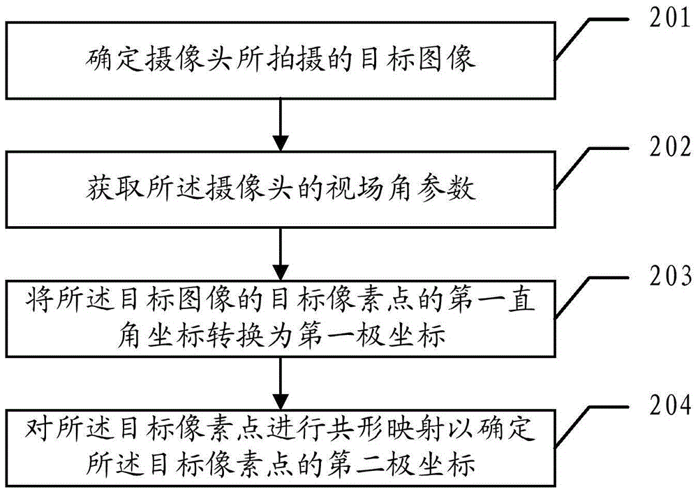
[0179] The following combination figure 2 Shown is a detailed description of an image correction method provided in an embodiment of the present invention;

[0180] 201. Determine the target image taken by the camera;

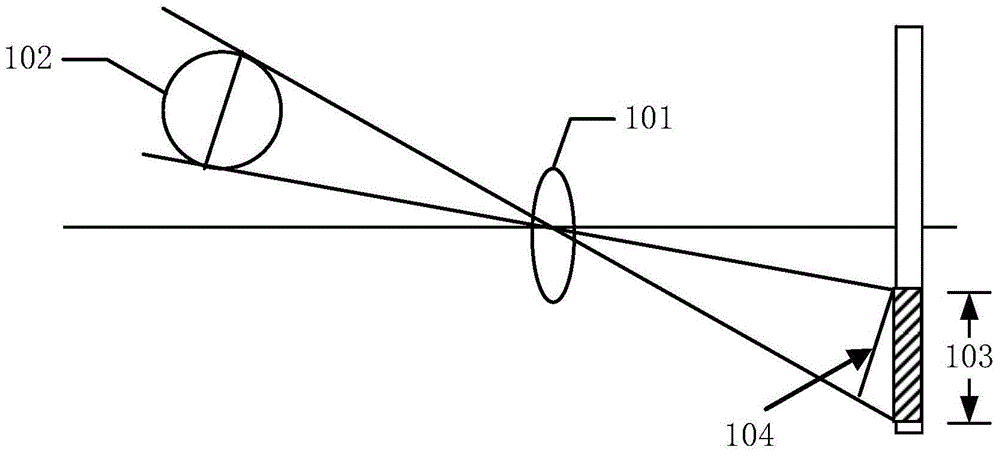
[0181] This embodiment does not limit the camera. For example, the camera may be a camera set on a mobile phone, optionally a front camera set on a mobile phone, or a camera set on a camera, or, for example, a tablet The camera, etc., as long as the camera meets the linear perspective relationship;

[0182] In this embodiment, it is first determined that the image taken by the camera is the target image.

[0183] 202. Obtain a field of view parameter of the camera.

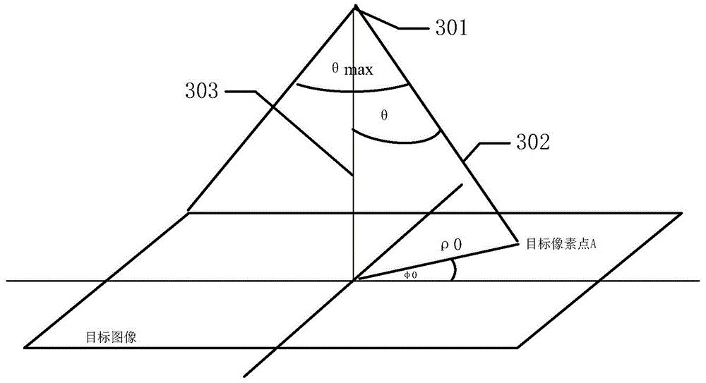
[0184] Wherein, the field of view parameter is the maximum field of view θ of the camera max And with the θ max The polar coordinate radius of the corresponding pixel ρ max ;

[0185] This embodiment does not limit how to obtain the field of view parameters. For example, the field of view parameters may ...


PUM


Abstract

The embodiment of the invention discloses an image correcting method and a camera. The image correcting method comprises the steps as follows: determining a target image shot by the camera; obtaining a field angle parameter of the camera; converting first right angle coordinates of target pixel points of the target image into first polar coordinates, wherein the target pixel points are all pixel points of the target image or partial pixel points meeting a first preset requirement; performing conformal mapping to the target pixel points so as to determine second polar coordinates of the target pixel points. The correcting method described in the embodiment could be used for automatically correcting the target image. The conformal mapping performed to the target image can hold the shape of the shot object so as to avoid the distortion of the shot object. If the target image contains a facial image, the correcting method showed by the embodiment could be used for automatically correcting the facial image without manual manipulation of a user.

Description

Technical field [0001] The invention relates to the field of image processing, in particular to an image correction method and a camera. Background technique [0002] The process of taking pictures is actually projecting objects in a three-dimensional space onto a two-dimensional plane for imaging. This imaging process is a projection from a high-dimensional space to a low-dimensional space. Different cameras may have different imaging relationships, such as fisheye lenses and ordinary lenses. For a general aberration-corrected camera, the imaging process can be regarded as a small hole imaging device. The small hole imaging process is a linear perspective projection, and there are often some perspective distortions. For example, objects farther from the camera will appear smaller in the photo than objects closer. [0003] Such as figure 1 As shown, the lens 101 is an ideal lens, the object 102 is a sphere in the object space, the image of the object 102 after the aberration corr...

Claims


Application Information

Patent Timeline
IPC IPC(8): H04N13/00H04N13/02G06T7/00
Inventor 戴俊李健王铭学
Owner HUAWEI TECH CO LTD
Why Eureka
Try Eureka