Cutter for uterus resection operation

A hysterectomy and knife technology, applied in the field of medical devices, can solve the problems of heavy workload for doctors, long time required, poor results, etc., and achieve the effect of improving surgical efficiency, reducing pain, and having a reasonable structure

Active Publication Date: 2015-10-28
HUZHOU MATERNITY & CHILD CARE HOSPITAL
View PDF12 Cites 1 Cited by
  • Summary
  • Abstract
  • Description
  • Claims
  • Application Information

AI Technical Summary

Problems solved by technology

At present, the relevant derivative instruments are mainly aimed at the separation of the uterus from the surrounding tissues. In clinical practice, the separated uterine body is often too large to be taken out directly from the vagina, and it needs to be cut into small pieces before taking it out. It takes a long time, the workload of the doctor is heavy, the effect is not good, and it is easy to touch the adjacent organs

Method used


Image

  • Cutter for uterus resection operation
  • Cutter for uterus resection operation
  • Cutter for uterus resection operation

Examples


Embodiment 1

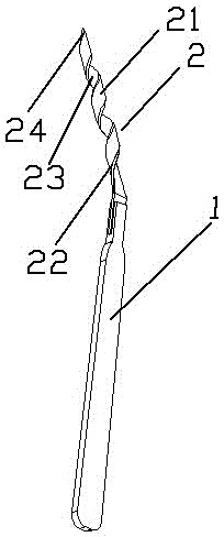
[0023] as attached figure 1 The shown cutter is used for hysterectomy, and includes a knife handle 1 and a sheet-shaped cutting knife 2 installed on the knife handle 1. The cutting knife 2 includes a knife back 21 and a knife extending outward from the knife back 21 for cutting The two blades 22 of the uterus, the blades 22 are spirally arranged along the central axis forming an angle α with the vertical axis of the knife handle 1, the angle α is an obtuse angle, which is 135° in this embodiment, and The helical angle of the blades 22 gradually decreases from the top of the tool to one end of the handle 1; adjacent blades 22 form a longitudinal channel 23 with a smooth arc-shaped surface leading to the direction of the handle 1 . The blade 2 forms a breakout tip 24 at the top of the knife where the tip of the blade portion 22 converges into a point.

Embodiment 2

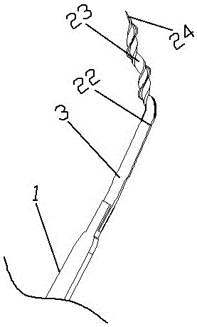
[0025] as attached figure 2 The shown cutter for hysterectomy comprises a knife handle 1, a connecting neck mounted on the knife handle 2 and a sheet cutter 2 integrated with the connecting neck. The cutting knife 2 includes a knife back 21 and a knife back 21 are three blades 22 extending outwards for cutting the uterus. The blades 22 are arranged helically along the central axis at an angle α of 110° with the vertical axis of the knife handle 1, and the blades 22 The helical angle gradually decreases from the top of the tool to one end of the handle 1; a longitudinal channel 23 leading to the direction of the handle 1 is formed between adjacent blades 22, and its width gradually decreases from the top of the tool to one end of the handle 1. increase. The blade 2 forms a breakout tip 24 at the top of the knife where the tip of the blade portion 22 converges into a point.

Embodiment 3

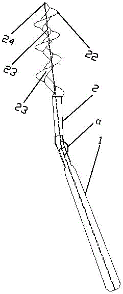
[0027] as attached image 3 The shown cutter for hysterectomy comprises a knife handle 1, a connecting neck mounted on the knife handle 2 and a sheet cutter 2 integrated with the connecting neck. The cutting knife 2 includes a knife back 21 and a knife back 21, three blades 22 extending outwards for cutting the uterus. The blades 22 are spirally arranged along the central axis forming an angle α with the vertical axis of the knife handle 1, and the angle α is 150°. And the helix angle of the blade portion 22 gradually decreases from the top of the tool to one end of the handle 1; between adjacent blade portions 22, a longitudinal channel 23 with a smooth arc-shaped channel surface leading to the direction of the handle 1 is formed, Its width gradually increases from the top of the cutter to one end of the handle 1 . The blade 2 forms a breakout tip 24 at the top of the knife where the tip of the blade portion 22 converges into a point.

[0028] When using, it is necessary to...


PUM


Abstract

The invention belongs to the field of medical apparatus, and relates to a cutter for a uterus resection operation. The cuter comprises a cutter handle and a cutting knife installed on the cutter handle, and is characterized in that the cutting knife comprises a knife back portion and at least one lade portion extending out from the knife back portion towards an outer side for cutting a uterus, wherein the blade portion is spirally arranged along a central axis forming an included angle alpha with the vertical axis of the cutter handle, the included angle alpha is an obtuse angle. The cutter provided by the invention is reasonable in structure and convenient to operate. For the condition that a uterus body is too large to be removed easily, the cutter can efficiently cut up and remove the uterus body, greatly improves the operation efficiency and mitigates the pain of a patient.

Description

technical field [0001] The invention relates to a surgical knife, in particular to a knife for hysterectomy, belonging to the field of medical instruments. Background technique [0002] Hysterectomy approaches include transabdominal, transvaginal, and laparoscopic. Compared with classic abdominal hysterectomy, vaginal hysterectomy and laparoscopic hysterectomy have the advantages of less trauma and faster recovery, and are easily accepted by patients. At the same time, vaginal hysterectomy has the disadvantages of small surgical field of view, difficult exposure and operation, and easy damage to adjacent organs. Therefore, in recent years, some special instruments for coordinating with minimally invasive hysterectomy have also been derived, such as the patent No. 20102021 6262.9, the invention called the cup type uterine lifter, which can play a good effect in the operation process. At present, the relevant derivative devices are mainly aimed at the separation of the ut...

Claims


Application Information

Patent Timeline
Patent Type & Authority Applications(China)
IPC IPC(8): A61B17/42A61B17/32
CPCA61B17/32A61B17/42A61B2017/320024A61B2017/4216
Inventor 任月芳万择秋吴晓云
Owner HUZHOU MATERNITY & CHILD CARE HOSPITAL
Why Eureka
Try Eureka