Eureka AIR delivers breakthrough ideas for toughest innovation challenges, trusted by R&D personnel around the world.

Head boring machine used for machining steel pipes

A head cutting machine and steel pipe technology, which is applied in the field of steel pipe processing, can solve the problems of small application range and high production cost, and achieve the effects of increasing application range, improving work efficiency, and reducing costs

Inactive Publication Date: 2015-10-28
李千林
View PDF6 Cites 0 Cited by
  • Summary
  • Abstract
  • Description
  • Claims
  • Application Information

AI Technical Summary

Problems solved by technology

[0003] The purpose of the present invention is to overcome the problems of small application range and high production cost of the existing steel pipe cutting equipment, and provide a head cutting machine for steel pipe processing with high work efficiency, convenient operation and wide application range, which reduces many The cost of a set of steel pipe cutting equipment

Method used


Image

  • Head boring machine used for machining steel pipes
  • Head boring machine used for machining steel pipes

Examples


Embodiment Construction

[0011] The present invention will be described in more detail below in conjunction with the accompanying drawings.

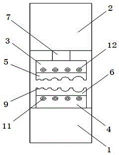
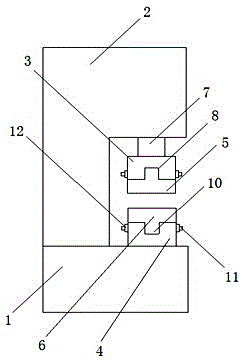
[0012] as attached figure 1 with 2 Shown:

[0013] A head cutting machine for processing steel pipes, comprising a base 1, a main machine 2, an upper mounting block 3, a lower mounting block 4, an upper pressing block 5 and a lower pad 6, wherein the main machine 2 is set on the base 1, the upper mounting block 3 is set on the main machine 2 through the lifting rod 7, and the mounting groove 8 is arranged on the upper mounting block 3, and the lifting rod 7 is used to facilitate the rising or falling of the upper mounting block 3, thereby realizing the For the cutting operation of the steel pipe, the lower mounting block 4 is arranged on the base 1, and the mounting groove 8 is arranged on the lower mounting block 4, and the punching hole 9 and the clamping block 10 are arranged on the upper pressing block 5, and The clamping block 10 is fixed in the installa...


PUM


Abstract

The invention provides a head boring machine used for machining steel pipes. The head boring machine comprises a base, a host machine body, an upper installing block, a lower installing block, an upper pressing block and a lower cushion block. The head boring machine is characterized in that the host machine body is arranged on the base, the upper installing block is arranged on the host machine body through a lifting rod, installing grooves are formed in the upper installing block, the lower installing block is arranged on the base, installing grooves are formed in the lower installing block, the upper pressing block is provided with punching holes and clamping blocks, the clamping blocks are fixed into the installing grooves in the upper installing block through connecting rods and installing nuts, the lower cushion block is provided with punching holes and clamping blocks, and the clamping blocks are fixed into the installing grooves in the lower installing block through connecting rods and installing nuts. According to the head boring machine, as the upper pressing block and the lower cushion block are provided with the punching holes corresponding one to one, and the multiple punching holes are of semicircular structures with different radiuses, the head boring machine can carry out head boring on the steel pipes of multiple specifications, the application range of the head boring machine is enlarged, cost of multiple head boring machines for the steel pipes is reduced, and the efficiency of the head boring machine for the steel pipes is improved.

Description

technical field [0001] The invention relates to the technical field of steel pipe processing, in particular to a head cutting machine for steel pipe processing. Background technique [0002] At present, in the steel pipe processing process, the steel pipe needs to be cold-drawn. In order to facilitate the cold-drawing operation of the steel pipe, the steel pipe needs to be cut before the steel pipe is cold-drawn. Carrying out the head cutting operation on a steel pipe reduces the scope of application of the steel pipe head cutting equipment and increases the cost of multiple sets of steel pipe head cutting equipment. Contents of the invention [0003] The purpose of the present invention is to overcome the problems of small application range and high production cost of the existing steel pipe cutting equipment, and provide a head cutting machine for steel pipe processing with high work efficiency, convenient operation and wide application range, which reduces the number of...

Claims


Application Information

Patent Timeline
IPC IPC(8): B21C5/00
Inventor 李千林周晓明
Owner 李千林
Why Eureka
Eureka Blog
Learn More