Main reducing gear shell and main reducing assembly

A technology of the main reducer and oil baffle, which is applied to transmission parts, components with teeth, belts/chains/gears, etc., which can solve the difficulty of universalizing the main reducer shell, increase product types and development costs, and reduce Issues such as the versatility of the main reduction assembly in the drive axle have achieved strong market promotion value, high support rigidity, and reduced development costs

Active Publication Date: 2015-10-28
SHAANXI HANDE AXLE CO LTD
View PDF5 Cites 6 Cited by
  • Summary
  • Abstract
  • Description
  • Claims
  • Application Information

AI Technical Summary

Problems solved by technology

[0002] The main reducer assembly is an important part of the automobile drive axle. It plays the role of reducing the speed and increasing the torque in the transmission system. Among the existing automobile drive axle products, it is used for the main reducer assembly of engineering vehicles, buses and trucks. Most of the parts in Chengzhong are common, but it is difficult to achieve universality for the main reducer housing in the main reducer assembly, because the difference between the front and rear axles and the upper and lower offsets of the active and passive gears will cause The lubricating oil passages of the active bevel gear bearings are different, so two kinds of main reducer shells or two bearing seats must be designed in the design to meet the lubrication requirements of the bearings under the different situations of the front and rear axles and the vertical offset of the active and passive gears. This not only greatly reduces the versatility of the main reduction assembly in the drive axle, but also increases the product variety and development costs, especially for medium and heavy vehicles

Method used


Image

  • Main reducing gear shell and main reducing assembly
  • Main reducing gear shell and main reducing assembly
  • Main reducing gear shell and main reducing assembly

Examples


Embodiment Construction

[0026] The technical solution of the invention will be described in detail below in conjunction with the accompanying drawings, so that those skilled in the art can understand the solution of the present invention more clearly, but the protection scope of the present invention is not limited thereby.

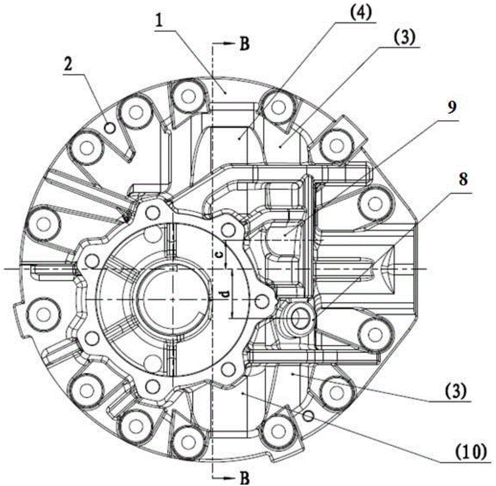
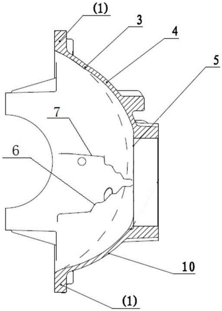
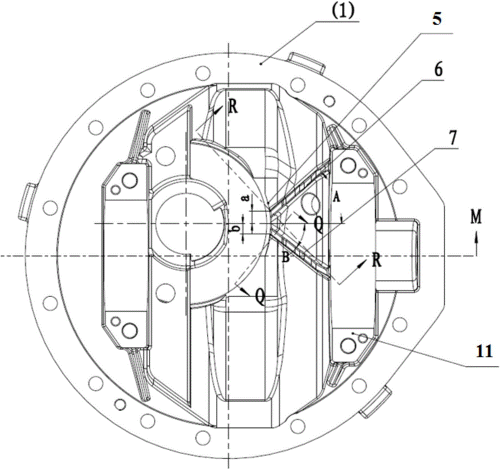
[0027] combined with figure 1 to attach image 3 As shown, the main reducer housing provided by the present invention includes a large surface 1 for reducing the casing, a rotating base 3, a first raised arc 4, a second raised arc 10 and a bearing mounting hole 5. The reduced casing The large surface 1 has an approximate ring shape as a whole, and extends inwardly along the inner edge of the ring to form the rotating base 3 , and the rotating base 3 protrudes from the inner side along the axial direction of the ring to form the convex arc , the bearing seat installation hole 5 is formed on the inner side of the raised arc, wherein the bearing seat installation hole 5 preferably...


PUM


Abstract

The invention provides a main reducing gear shell. The main reducing gear shell comprises a large reducing shell face, a rotating base body, a protruding circular arc and a bearing pedestal mounting hole. A circular arc face is formed by the rotating base body and the protruding circular arc, and a first oil stopping plate and a second oil stopping plate are arranged at the concave position of an inner cavity of the circular arc face, are distributed on the two sides of the mounting horizontal line of the bearing pedestal mounting hole and extend to the edge from the bearing pedestal mounting hole; a first oil adding hole boss and a second oil adding hole boss which can machine oil adding holes communicated with a lubricating oil cavity are cast on the outer surface of the rotating base body; the oil stopping plates of an innovative structure are arranged in the main reducing gear shell, and a protruding structure is innovatively designed on the shell, so that integration of an oil inlet way and an oil returning way is achieved; under the four states of forward rotation and reverse rotation of lower offset and forward rotation and reserve rotation of upper offset of a driving conical gear, a main reducing assembly supporting bearing is lubricated; and generality of the main reducing gear shell and a main reducing assembly is greatly improved, and the development cost of an axle is reduced.

Description

technical field [0001] The invention relates to the technical field of auto parts, in particular to a main reducer housing and a main reduction assembly of a medium-heavy vehicle axle. Background technique [0002] The main reducer assembly is an important part of the automobile drive axle. It plays the role of reducing the speed and increasing the torque in the transmission system. Among the existing automobile drive axle products, it is used for the main reducer assembly of engineering vehicles, buses and trucks. Most of the parts in Chengzhong are common, but it is difficult to achieve universality for the main reducer housing in the main reducer assembly, because the difference between the front and rear axles and the upper and lower offsets of the active and passive gears will cause The lubricating oil passages of the active bevel gear bearings are different, so two kinds of main reducer shells or two bearing seats must be designed in the design to meet the lubrication ...

Claims


Application Information

Patent Timeline
Patent Type & Authority Applications(China)
IPC IPC(8): F16H57/02F16H57/021F16H57/04
CPCF16H57/02F16H57/021F16H57/0424F16H57/0427F16H57/0469F16H2057/0206
Inventor 郭鸿瑞李静高刚刚孙超徐燕
Owner SHAANXI HANDE AXLE CO LTD
Why Eureka
Try Eureka