Microscope object stage specimen fixator automatic control system

An automatic control system and specimen fixation technology, used in microscopes, instruments, optics, etc., can solve the problems of relying on manual adjustment and lack of flexibility, and achieve the effect of accurate movement control.

Inactive Publication Date: 2015-10-28
苏州南光电子科技有限公司
View PDF8 Cites 3 Cited by
  • Summary
  • Abstract
  • Description
  • Claims
  • Application Information

AI Technical Summary

Problems solved by technology

[0008] The technical problem to be solved by the present invention is to overcome the deficiencies of the prior art, provide an automatic control system for the specimen holder of the microscope stage, and solve the problem that the existing specimen holder on the microscope stage needs to manually move the specimen, so that its The imaging position in the eyepiece changes. This method relies on manual adjustment, which is not flexible enough.

Method used


Image

  • Microscope object stage specimen fixator automatic control system

Examples


Embodiment 1

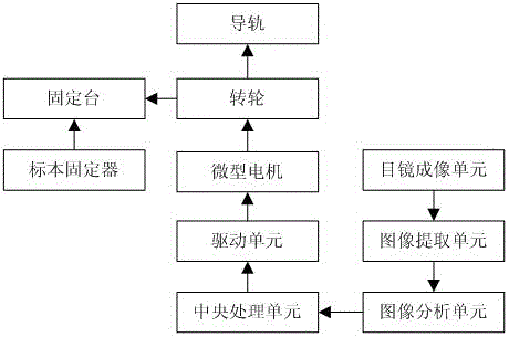
[0024] The automatic control system adopted in this embodiment includes: a transmission mechanism, a micro motor, a drive unit, a central processing unit, an eyepiece imaging unit, an image extraction unit, and an image analysis unit, wherein the eyepiece imaging unit is arranged on the eyepiece for placing the eyepiece The image is generated from the sample on the image; the image extraction unit is used to extract the generated image in real time; the image analysis unit is used to analyze the extracted image, judge the coverage area of ​​the sample in the image to obtain a coverage value; The central processing unit is used to judge according to the coverage value, and generates a control signal when the coverage value is lower than the preset coverage value; the drive unit is used to convert the control signal into a drive signal output; the micro motor , for generating a driving force according to the driving signal, and the driving force drives the transmission mechanism ...

Embodiment 2

[0027] In this embodiment, different from the embodiment, the automatic control system includes: a transmission mechanism, a micro motor, a drive unit, a central processing unit, an eyepiece imaging unit, an image extraction unit, and an image analysis unit, wherein the eyepiece imaging unit is set On the eyepiece, it is used to generate an image of the specimen on the eyepiece; and, the transmission mechanism includes a guide rail, a runner and a fixed platform, and the guide rail is fixedly arranged on the surface of the stage; the center of the runner is fixedly connected to the guide One end of the rod, and the other end of the guide rod are fixedly connected with the rotating shaft of the micro motor; the fixed table is fixed on the rotating wheel through a bracket, and a specimen holder is arranged on the surface of the fixed table. The structure utilizes the way of rotating and moving in the guide rail to flexibly realize the movement, improve the flexibility and save th...


PUM


Abstract

The invention discloses a microscope object stage specimen fixator automatic control system comprising a transmission mechanism, a micro-motor, a driving unit, a central processing unit, an eye lens imaging unit, an image extraction unit and an image analysis unit. The eye lens imaging unit is arranged on an eye lens and used for generating an image of a specimen on the eye lens. The image extraction unit is used for extracting images in real time. The image analysis unit is used for analyzing the extracted images and judging cover area of the specimen in the images so as to acquire a cover value. The central processing unit is used for judgment according to the cover value. When the cover value is lower than the preset cover value, a control signal is generated. The driving unit is used for converting the control signal into a driving signal to be outputted. The micro-motor is used for generating driving force. The transmission mechanism is used for driving a specimen fixator to linearly move. Movement of the specimen fixator can be rapidly and accurately realized without artificial adjustment.

Description

technical field [0001] The invention relates to an automatic control system for a specimen holder of a microscope stage, belonging to the technical field of microscope control. Background technique [0002] A microscope is an optical instrument composed of a lens or a combination of several lenses, and it is a sign that human beings have entered the atomic age. It is mainly used to magnify tiny objects into instruments that can be seen by human eyes. Microscopes are divided into optical microscopes and electron microscopes: Optical microscopes were first invented by Jansen and his sons in the Netherlands in 1590. The current optical microscope can magnify the object by 1600 times, and the minimum resolution limit reaches 0.1 micron. The length of the domestic microscope mechanical tube is generally 160mm. [0003] Microscopes can be classified into optical microscopes and electron microscopes based on their microscopic principles. For an optical microscope, it usually con...

Claims


Application Information

Patent Timeline
Patent Type & Authority Applications(China)
IPC IPC(8): G02B21/26G02B21/34
CPCG02B21/26G02B21/32G02B21/34
Inventor 童学权
Owner 苏州南光电子科技有限公司
Why Eureka
Try Eureka